Posts | Comments

Planet Arduino

Archive for the ‘PWM’ Category

May
12

Simple Infrared PWM on Arduino

arduino, IR, PWM Comments Off on Simple Infrared PWM on Arduino 

56kHz-50-percent

by analysir.com:

We are often asked on discussion boards, about conflicts between IRremote or IRLib and other Arduino Libraries. In this post, we present a sketch for ‘Simple Infrared PWM on Arduino’. This is the first part in a 3 part series of posts. Part 1 shows how to generate the simple Infrared carrier frequency on Arduino, using any available IO pin and without conflicting with other libraries. Part 2 will show how to send a RAW infrared signal using this approach and Part 3 will show how to send a common NEC signal from the binary or HEX value.

Simple Infrared PWM on Arduino – [Link]

Oct
27

Arduino solar charge controller and energy monitor

arduino, charging, Energy, monitor, PWM, solar, Test/Measurements Comments Off on Arduino solar charge controller and energy monitor 

solarcontroller

by deba168 @ instructables.com:

One year ago, I began building my own solar system to provide power for my village house.Initially I made a LM317 based charge controller and an Energy meter for monitoring the system.Finally I made PWM charge controller.In April-2014 I posted my PWM solar charge controller designs on the web,it became very popular. Lots of people all over the world have built their own. So many students have made it for their college project by taking help from me.I got several mails every day from people with questions regarding hardware and software modification for different rated solar panel and battery. A very large percentage of the emails are regarding the modification of charge controller for a 12Volt solar system.

Arduino solar charge controller and energy monitor - [Link]

Sep
23

On Arduino due PWM frequency

arduino, ATmega328P, PWM Comments Off on On Arduino due PWM frequency 

pwm_frequency-600x433

Kerry D. Wong writes:

I just got myself a couple of Arduino Due boards. While they were released almost two years ago, I have not really got a chance to look at these until quite recently. Arduino Due is based on Atmel’s ATSAM3x8E 32-bit ARM Cortext-M3 processor. The processor core runs at 84 MHz, which is significantly faster than its 8-bit AVR counterpart ATmega328p which runs at 16 MHz. For an ATmega328p, the highest achievable PWM frequency is 8Mhz (square wave), so we should be able to generate much higher frequency signals on an Arduino Due. But how high can we go? Let’s find out.

[via]

On Arduino due PWM frequency - [Link]

Sep
08

Meter clock: keeping “current” time

analog, arduino, clock, PWM, timer Comments Off on Meter clock: keeping “current” time 

NewImage39

Meter clock: keeping “current” time. Read more about the clock:

I’ve seen a few meter clocks in my travels of the web, and I love the idea. A few days ago, I decided that I must have one of my own. Such began the “How to do it” pondering cycle. I had seen builds where the face plate of the meter is replaced. This works, but I wanted to try and find a way to do it without modifying the meter, if possible. After some more ponderation, I came up with what I think is a serviceable idea.

I came across this style of milliamp meter on Amazon. They’re not quite 0-60 mA, but the 0-100 mA (a 0-20mA meter for the hours) is close enough. And they were cheap. So yay.

Part of my requirements were that the clock run off of an Arduino Pro Mini I had lying around, and with minimal additional parts. In order to drive the meters with some degree of precision, I would use the PWM pins to vary the effective voltage across a resistor in series with the meter. This would, by the grace of Ohm’s Law, induce a current that, based on the PWM duty cycle, would be scaled in such a way as to move the needle on the meter to the corresponding hour, minute, or second.

One minor issue came up in the form of the max current the GPIO pins on the ATMega328 chip can source/sink. The pins can source/sink a maximum of 40mA, a bit far from the 60mA needed for the minutes and seconds meters. Enter the transistor.

Using a simple NPN transistor switch circuit, I was able to provide the current for the minute and second meters from the 5V supply. The PWM signals switch the respective transistors on and off, effectively varying the voltage across the resistors in series with the meters.

The resistor between 5V and the meter is actually 2 1/4 watt 100 Ohm resistors in parallel for an effective resistance of 50 Ohms. The two in parallel was necessary as 5V x 0.06A = 0.3W (more than 0.25 that a single 1/4W resistor can handle safely).

[via]

Meter clock: keeping “current” time - [Link]

Aug
23

Galileo now runs Windows

arduino, Galileo, intel, PWM Comments Off on Galileo now runs Windows 

galileo2

by elektor.com:

Microsoft have released a non-commercial version of Windows based on Windows 8.1 to run on the Intel Galileo development board. A spokesperson for Microsoft said “This preview Windows image is another opportunity for makers and developers to create, generate new ideas and provide feedback to help Microsoft continue making Windows even better on this class of device”.

The board and OS are part of the Windows Developer Program for the IoT (Internet of Things) which Microsoft hopes will encourage developers of Internet-connected devices to experiment with Windows platforms. The Galileo kits include the standard Arduino Wiring API and a subset of the Win32 API. At the moment Linux is the OS of choice among makers and for the next generation of devices but Microsoft hopes to break that dominance. Intel released an update to the original Galileo Gen 1 board earlier this month which features an improved control of its PWM (Pulse Width Modulated) output signals to make the board better suited for the management of 3D printers and robotic applications. Galileo Gen 2 can also be powered from the Ethernet port which the earlier Gen 1 version did not allow.

Galileo now runs Windows - [Link]

Aug
22

How to make a simple wav player by using Arduino

arduino, PCM, PWM, WAV Comments Off on How to make a simple wav player by using Arduino 

Arduino-Simple-WAV-Player

Integrated with the homemade low-pass filter, this Arduino-based simple WAV player is to send out PWM signal generated by UNO,

then through the low-pass filter and make the PCM data stored in the flash of UNO into sounds. Basically, the player cannot be regarded

as a pure WAV playback, because by extracting the data from the WAV file and storing it in an array format in UNO, this tutorial is for reference.

You can make SD card based WAV player by referring to this idea.

How to make a simple wav player by using Arduino - [Link]

Jul
22

Monster 100W LED Flashlight Produces a Whopping 8500lm!

100W LED, 100W LED light, arduino hacks, boost converter, flashlight, led hacks, PWM Comments Off on Monster 100W LED Flashlight Produces a Whopping 8500lm! 

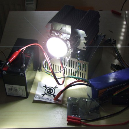
100W LED Flashlight

[Yannick] got a hold of a 100W LED diode recently, and like any self-respecting hacker, he just had to turn it into a ridiculously over powered flash light.

The tricky thing about these diodes is that they need a high amount of DC voltage, anywhere from 32-48V typically. [Yannick's] using a 12V sealed lead acid battery coupled with a 600W constant current boost converter which ups it to 32V at around 3.2A. He also managed to find a giant aluminum heat-sink to keep the diode from getting too hot. A 120mm fan helps to keep the heat sink nice and cool, which allows the light to be run constantly without fear of burning it out. But just in case he also has an Arduino monitoring the temperatures — oh and it provides PWM control to adjust the brightness of the light!

To focus the flashlight he bought a proper lens and reflector which can be mounted directly to the diode. At full power the LED puts out around 8500lm, which is brighter than almost all consumer projectors available — or even the high beams of a car!

This isn’t the first time we’ve seen a 100W LED diode being used as a flashlight, but the builds are definitely getting fancier!


Filed under: Arduino Hacks, led hacks
Jul
22

Monster 100W LED Flashlight Produces a Whopping 8500lm!

100W LED, 100W LED light, arduino hacks, flashlight, led hacks, PWM Comments Off on Monster 100W LED Flashlight Produces a Whopping 8500lm! 

100W LED Flashlight

[Yannick] got a hold of a 100W LED diode recently, and like any self-respecting hacker, he just had to turn it into a ridiculously over powered flash light.

The tricky thing about these diodes is that they need a high amount of DC voltage, anywhere from 32-48V typically. [Yannick's] using a 12V sealed lead acid battery coupled with a 600W constant current boost converter which ups it to 32V at around 3.2A. He also managed to find a giant aluminum heat-sink to keep the diode from getting too hot. A 120mm fan helps to keep the heat sink nice and cool, which allows the light to be run constantly without fear of burning it out. But just in case he also has an Arduino monitoring the temperatures — oh and it provides PWM control to adjust the brightness of the light!

To focus the flashlight he bought a proper lens and reflector which can be mounted directly to the diode. At full power the LED puts out around 8500lm, which is brighter than almost all consumer projectors available — or even the high beams of a car!

This isn’t the first time we’ve seen a 100W LED diode being used as a flashlight, but the builds are definitely getting fancier!


Filed under: Arduino Hacks, led hacks
Jun
10

PWM motor speed control using Arduino

arduino, motor, PWM Comments Off on PWM motor speed control using Arduino 

motor-speed-control-arduino

praveen @ circuitstoday.com writes:

PWM or pulse width modulation is a very common method used for controlling the power across devices like motor, light etc. In PWM method the power across the load is controlled by varying the duty cycle of the drive signal. More the duty cycle more power is delivered across the load and less the duty cycle, less power is delivered across the load. A hex keypad is used for controlling the speed. The speed can be varied in seven steps using the hex keypad. Arduino UNO is the type os arduino development board used in this circuit. The circuit diagram of the PWM motor speed control using arduino is shown in the figure below.

PWM motor speed control using Arduino - [Link]

Jun
08

PWM-Servo-Tester

Having the right tool for the job makes all the difference, especially for the types of projects we feature here at Hackaday. [Jan_Henrik's] must agree with this sentiment, one of his latest projects involves building a tool to generate a PWM signal and test servos using an Attiny25/45/85.

Tools come in all kinds of different shapes and sizes. Even if it might not be as widely used as [Jan_Henrik's] earlier work that combines an oscilloscope and signal generator, having a tool that you can rely upon to test servos and generate a PWM can be very useful. This well written Instructable provides all the details you need to build your own, including the schematic and the necessary code (available on GitHub). The final PWM generator looks great. For simple projects, sometimes a protoboard is all you need. It would be very cool to see a custom PCB made for this project in the future.

What tools have you build recently? Indeed, there is a tool for every problem. Think outside the (tool) box and let us know what you have made!


Filed under: Arduino Hacks, tool hacks


  • Newsletter

    Sign up for the PlanetArduino Newsletter, which delivers the most popular articles via e-mail to your inbox every week. Just fill in the information below and submit.

  • Like Us on Facebook