Posts | Comments

Planet Arduino

Archive for the ‘Magnetometer’ Category

I recently added a new feature to the magnetometer remote sensor unit firmware. To help indicate when it is within radio communication range of the base unit an LED is turned on at the start of a message communication. When the sensor unit receives the acknowledgement from the base unit of successful message receipt the LED is switched off. In normal operation the LED should blink briefly every 30 seconds, after each sampling interval. If the LED remains on it indicates a problem with the radio link. For the initial installation the sampling time can be reduced to 5 seconds for to obtain faster feedback of whether communication is successful or not.

Improvements for battery-powered operation

Indicating link errors by using an LED is convenient during installation but the power wasted after installation is not compatible with battery-powered operation. To save power the LED is used only the first 15 minutes of operation. Only user-initiated reset actions (power on or reset switch pressed) cause the LED to be used, resets from by the watchdog timer or brown-out detector are ignored. The cause of the reset is detected by examining the microcontroller's status register (MCUSR).


Communication timeout feature added

I've also added a timeout which detects when communication has been lost for an extended period. The microcontroller system is rebooted in the hope that the error is recoverable. Loss of communication, along with low battery status, can also be sensed and reported by running the latest version of the data plotting software on the Raspberry Pi. If either error is detected a message can be sent via email, Twitter or Facebook.


Oct
27

Magnetometer progress report: link indicator LED

arduino, AuroraWatchNet, Magnetometer Comments Off on Magnetometer progress report: link indicator LED 

I recently added a new feature to the magnetometer remote sensor unit firmware. To help indicate when it is within radio communication range of the base unit an LED is turned on at the start of a message communication. When the sensor unit receives the acknowledgement from the base unit of successful message receipt the LED is switched off. In normal operation the LED should blink briefly every 30 seconds, after each sampling interval. If the LED remains on it indicates a problem with the radio link. For the initial installation the sampling time can be reduced to 5 seconds for to obtain faster feedback of whether communication is successful or not.

Improvements for battery-powered operation

Indicating link errors by using an LED is convenient during installation but the power wasted after installation is not compatible with battery-powered operation. To save power the LED is used only the first 15 minutes of operation. Only user-initiated reset actions (power on or reset switch pressed) cause the LED to be used, resets from by the watchdog timer or brown-out detector are ignored. The cause of the reset is detected by examining the microcontroller's status register (MCUSR).


Communication timeout feature added

I've also added a timeout which detects when communication has been lost for an extended period. The microcontroller system is rebooted in the hope that the error is recoverable. Loss of communication, along with low battery status, can also be sensed and reported by running the latest version of the data plotting software on the Raspberry Pi. If either error is detected a message can be sent via email, Twitter or Facebook.


Three-axis magnetometer sensor unit
Three-axis sensor unit. The RJ-45 connector is for power and I2C data signals, not Ethernet.

AuroraWatchNet is a network of magnetometers for auroral alerts and citizen science. Whilst the  magnetometer is intended to function with one single-axis FLC100 sensor from Stefan-Mayer Instruments I have designed the system to support 3-axis operation by mounting 3 sensor boards at 90° to each other using just standard right-angle PCB connectors. This approach avoids the requirement for external mounting hardware which would be expensive to manufacture.

The power supply (a charge-pump DC-DC converter), temperature sensor and RJ-45 connector are fitted to just one circuit board. It is possible to use only one analogue-to-digital converter (ADC) but given their low cost it was presumed they would be fitted to all boards to enable simultaneous sampling of all 3 axes. The MCP3424 converter was chosen because eight options are available for the I2C address, thus jumpers can be fitted to select a unique address for every ADC on the I2C bus. This converter also features 4 input channels. All magnetometer outputs and the temperature sensor are connected to each ADC so that the spare channels can provide some redundancy in case of an ADC failure. The SYNC connectors of all sensors are linked to synchronise their excitation frequencies.

Several single-axis units have been built and one is in active use by AuroraWatch UK. The photograph above shows the first three-axis unit to be built. Initial testing indicates it functions as intended but the performance of 3 simultaneously-powered sensors in close proximity is yet to be established.


Mar
03

Three-axis sensor unit for AuroraWatchNet

AuroraWatch UK, AuroraWatchNet, Magnetometer Comments Off on Three-axis sensor unit for AuroraWatchNet 

Three-axis magnetometer sensor unit
Three-axis sensor unit. The RJ-45 connector is for power and I2C data signals, not Ethernet.

AuroraWatchNet is a network of magnetometers for auroral alerts and citizen science. Whilst the  magnetometer is intended to function with one single-axis FLC100 sensor from Stefan-Mayer Instruments I have designed the system to support 3-axis operation by mounting 3 sensor boards at 90° to each other using just standard right-angle PCB connectors. This approach avoids the requirement for external mounting hardware which would be expensive to manufacture.

The power supply (a charge-pump DC-DC converter), temperature sensor and RJ-45 connector are fitted to just one circuit board. It is possible to use only one analogue-to-digital converter (ADC) but given their low cost it was presumed they would be fitted to all boards to enable simultaneous sampling of all 3 axes. The MCP3424 converter was chosen because eight options are available for the I2C address, thus jumpers can be fitted to select a unique address for every ADC on the I2C bus. This converter also features 4 input channels. All magnetometer outputs and the temperature sensor are connected to each ADC so that the spare channels can provide some redundancy in case of an ADC failure. The SYNC connectors of all sensors are linked to synchronise their excitation frequencies.

Several single-axis units have been built and one is in active use by AuroraWatch UK. The photograph above shows the first three-axis unit to be built. Initial testing indicates it functions as intended but the performance of 3 simultaneously-powered sensors in close proximity is yet to be established.


The batteries expired in one of the AuroraWatchNet test magnetometers this week. I was expecting that to happen since the magnetometer wasn't operating in its low-power mode and the battery voltage from the two 1.5V alkaline cells had been hovering around 2V for some time. The Atmel ATmega1284P microcontroller is actually powered at 3.3V using a boost power supply. What I didn't expect was for the system to not start after replacing the battery. I could tell xboot was working since the LED flashed 3 times as usual after the reset button was pressed. After that the LED stayed on but nothing else happened, not even the start-up debug messages from the serial port. I guessed the flash program memory had somehow got corrupted.

I used the AVR Dragon to extract the contents of the flash memory (avrdude -P usb -c dragon_jtag -p atmega1284p -U flash:r:flash.img:r) and compared it against the saved raw image file using the linux split and cmp commands. Sure enough, three pages of flash memory were set to 0xFF, probably from some erroneous page clear operation. Brown-out detection was disabled by the fuse settings to save power. Big mistake! What I think happened was as the voltage dipped below its valid range the microcontroller started executing random commands, including 3 SPM page clears, one of which was the first page of flash which holds the interrupt vector table. Valid execution was doomed.

What I should have done was to enable brown-out detection in the fuses, 2.7V seems the most appropriate setting for an 8MHz clock and 3.3V operation. To save power during sleeping the brown-out detection can be disabled with a call to sleep_bod_disable(). Lesson learned!
Feb
10

The importance of brown-out detection

arduino, AuroraWatchNet, Calunium, Magnetometer Comments Off on The importance of brown-out detection 

The batteries expired in one of the AuroraWatchNet test magnetometers this week. I was expecting that to happen since the magnetometer wasn't operating in its low-power mode and the battery voltage from the two 1.5V alkaline cells had been hovering around 2V for some time. The Atmel ATmega1284P microcontroller is actually powered at 3.3V using a boost power supply. What I didn't expect was for the system to not start after replacing the battery. I could tell xboot was working since the LED flashed 3 times as usual after the reset button was pressed. After that the LED stayed on but nothing else happened, not even the start-up debug messages from the serial port. I guessed the flash program memory had somehow got corrupted.

I used the AVR Dragon to extract the contents of the flash memory (avrdude -P usb -c dragon_jtag -p atmega1284p -U flash:r:flash.img:r) and compared it against the saved raw image file using the linux split and cmp commands. Sure enough, three pages of flash memory were set to 0xFF, probably from some erroneous page clear operation. Brown-out detection was disabled by the fuse settings to save power. Big mistake! What I think happened was as the voltage dipped below its valid range the microcontroller started executing random commands, including 3 SPM page clears, one of which was the first page of flash which holds the interrupt vector table. Valid execution was doomed.

What I should have done was to enable brown-out detection in the fuses, 2.7V seems the most appropriate setting for an 8MHz clock and 3.3V operation. To save power during sleeping the brown-out detection can be disabled with a call to sleep_bod_disable(). Lesson learned!
Jan
13

Magnetometer progress report

AuroraWatchNet, Calunium, Magnetometer, RaspberryPi Comments Off on Magnetometer progress report 

About AuroraWatchNet

I am developing a simple, low-cost, battery-powered magnetometer for auroral alerts and citizen science. It is intended to be wireless to allow easy installation, a unique feature as far as I am aware. The magnetometer uses my own Calunium micro-controller board, which is an Arduino clone based on the ATmega1284P micrcontroller. Data is sent via a radio link to a Raspberry Pi base station which will then forward the data to AuroraWatch UK. I am hoping to deploy a network of such magnetometers in 2013 to enable AuroraWatch UK users to contribute data to improve the service. If you want to track the development then follow @aurorawatchnet on Twitter. 

The first AuroraWatchNet magnetometer is currently running in my garden. The environment is not ideal as I can see disturbances from cars and even the garage door being opened but it is convenient for testing and representative of what to expect from user-contributed data. I have been comparing the results from our SAMNET magnetometers with the AuroraWatchNet prototypes and generally the results are very encouraging given the difference in cost between the two systems. Now I can plot the AuroraWatchNet magnetometer data in the standard AuroraWatch UK style, using the same Octave code. Below is a comparison of today's plots. 

AuroraWatch UK

The data is taken from SAMNET's Lancaster magnetometer. The X axis is time and the Y axis shows the magnetic field strength in the direction of magnetic North (H component) in nanotesla (nT) relative to an unrecorded baseline. This exact plot appeared on AuroraWatch UK. We would normally expect cleaner data but our Lancaster site has recently been experiencing some interference.

SAMNET data from Lancaster, as used by AuroraWatch UK

AuroraWatchNet test magnetometers

The plots below correspond to the same time interval as the plot above. The first plot is from my garden magnetometer.

AuroraWatchNet data from near Lancaster.

The Y axis again records magnetic field strength but this time it is the absolute field. This magnetometer is operating in power-saving mode, turning off the sensor when not needed. This slightly increases the noise level but I hope will give one year of operation from two D cells.

Another AuroraWatchNet magnetometer has been deployed almost adjacent to the SAMNET magnetometer we already use for AuroraWatch. In this system the magnetometer sensor is continually powered, resulting in reduced noise levels. The alignment with magnetic North is only approximate. 


AuroraWatchNet data from the Lancaster University field station.

Conclusion

The AuroraWatchNet magnetometers are sufficiently sensitive and stable to make useful contributions for auroral detection and citizen science. My experience with the garden magnetometer suggests that in many cases performance will be limited by the noise at the site, rather than the magnetometer.
Dec
28

RFM12B shield for Raspberry Pi: Preliminary design

Magnetometer, RaspberryPi, RFM12B Comments Off on RFM12B shield for Raspberry Pi: Preliminary design 

RFM12B shield for Raspberry Pi
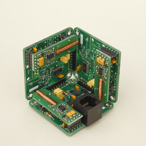
Raspberry Pi interface to the RFM12B radio module, with integrated ISP programmer. The cut-out is to enable the PCB to fit inside the Multicomp Raspberry Pi case.

Current status

Earlier in the year I posted a design for a wireless gateway for the Raspberry Pi. It featured interfaces for the Hope RFM12 and XBee (or Ciseco XRF) radio modules. Also included was an in-circuit serial programming (ISP) programming interface for Atmel microcontrollers. I later refined the ISP interface to include some protection for the Raspberry Pi by adding a buffer and FET switch. I have not yet tried accessing the RFM12B directly from the Pi but other people have had problems, mainly it seems because of the time-critical interrupt handling. I'm sure this problem will eventually be solved once the Eve Alpha boards become widely available. Martin Harizanov solved this problem by adding an Atmel ATtiny microcontroller to bridge between the UART interface on the Pi and the SPI interface on the RFM12B. I bought a bare PCB that did this from the Open Energy Monitor shop. I tested the RFM12Pi Raspberry Pi Expansion board communicating with one of my Calunium v2 development boards, everything worked. Martin chose the ATtiny84 microcontroller which has just 512 bytes of RAM. I would like to have a solution which more closely mimics the Ciseco XRF module that I am currently using, which has a 240 byte buffer. One reason for needing a larger buffer is that the radio protocol I am using supports over the air firmware updates, with the new firmware sent in 128 byte blocks. If I am to implement something with 240 byte transmit and receive buffers I will need a microcontroller with more than 512 bytes of RAM.
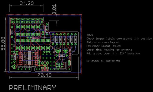
Preliminary design

Based on my previous work and inspired by Martin Harizanov's implementation I have designed a RFM12B shield for the Raspberry Pi with integrated ISP interface. The microcontroller on this board is the popular ATmega328P, as used in the Arduino. Including the ISP interface has considerably increased the size of the PCB but this is a price I am willing to pay. The board is intended to be used as part of the AuroraWatchNet magnetometer network and the ability to remotely update the firmware will be very useful, especially since I can already perform over-the-air firmware upgrades on the battery-powered Calunium node. Surface-mount passive components could be used to reduce the PCB size but this would be contrary to my goal of making the AuroraWatchNet magnetometers easy to build for novice constructors.

The 74LVC244 buffer has two 4-bit line drivers, allowing two independent ISP interfaces to be included. The first is for the on-board ATmega328P microcontroller, the second is wired to a standard Atmel ISP header to allow an external microcontroller to be programmed. It means that the ATmega1284P used in the remote Calunium of the AuroraWatchNet magnetometers can be programmed initially, or recovered in the case of an over-the-air firmware upgrade mistake.

I hope to have some circuit boards made in January 2013 so if you spot any mistakes please let me know as soon as possible!

Open source

The Eagle PCB design files for the RFM12B/ISP shield for Raspberry Pi are available on Github and are licensed under the Creative Commons Attribution-ShareAlike 3.0 Unported License.
Dec
12

RN-XV+SD shield

arduino, Calunium, Magnetometer Comments Off on RN-XV+SD shield 

RN-XV, SD and magnetometer shield
RN-XV+SD shield. Click on the image for an annotated version.

In my quest to make a low-power magnetometer for AuroraWatch UK there are two additional periphals needed: a Wifi connection for real-time data transfer and an SD card for configuration and data logging. I wasn't happy with any of the existing XBee or SD shields. Many of them use resistor-divider networks which prevent dual 3.3V/5V operation (very useful for development), and those which do use logic-level shifters seem to ignore the problem of mixing 3.3V devices with 5V ones.

In response to this need I designed my own shield. I investigated several Wifi modules, but the main contenders were the XBee wifi module and the similar RN-XV module made by Roving Networks. Although I like the idea of the SPI interface that the XBee module offers in the end I chose the RN-XV, partly because it was cheaper but also for its better availability. Both modules use the same pseudo-standard XBee footprint so to some extent either could be used, although the circuitry is designed for the UART interface and GPIOs of the RN-XV. I also included the circuitry for the PNI MicroMag3 module. This is outside the main shield area so as to be located away from the metal casing of the SD card and away from the Wifi module, which could cause interference. To test for temperature effects an LM61 temperature sensor can be used. Unlike the optional one on Calunium this is powered from a logic output for ultra-low power consumption. The shield is designed for Calunium, but will work with full functionality on the Arduino Mega2560. It will also operate on a standard Arduino but flow control and some of the GPIO features of the RN-XV are not available.

Fitting everything onto a 80 × 100mm PCB (the largest size possible in the free version of Cadsoft Eagle) was difficult so I chose to use surface-mount components. The many jumpers are included to make the board as flexible as possible. I sent the Gerber files to Iteadstudio for manufacture. For maximum yield I used very conservative 0.012" trace widths and 0.012" minimum separation, with 0.024" ground-pour isolation. The magnetometer circuitry is easily removed from the schematic and board design if it is not needed; on the manufactured boards the magnetometer section can be removed with a guillotine without affecting the rest of the circuitry. The cut-out is carefully arranged to avoid obstructing the reset button and the USB and JTAG connectors on Calunium.

RN-XV, SD and magnetometer shield on Calunium
RN-XV+SD shield on Calunium.

Eagle PCB design files available under the Creative Commons Attribution-ShareAlike 3.0 Unported (CC BY-SA 3.0) licence.


  • Newsletter

    Sign up for the PlanetArduino Newsletter, which delivers the most popular articles via e-mail to your inbox every week. Just fill in the information below and submit.

  • Like Us on Facebook