Posts | Comments

Planet Arduino

Archive for the ‘RaspberryPi’ Category

If you run an SSH server open to the whole internet you'll soon notice many attempts to break into your system using random username and password combinations. This 'noise' in the log files is annoying and might mean you miss an important message. If you are unlucky or use a common username and password your system might be compromised by one of these brute force attacks.

One method to drastically reduce the number of cracking attempts is to restrict access to the SSH server by IP address. This can done be done either by editing the SSH config file or by using configuring iptables. However this method requires valid users to have static IP addresses, something which most home users don't have. In many cases public key authentication is a better choice.

Use public key authentication

A better method to stop attackers from using random username and passwords is to switch off password authentication entirely and require public key authentication instead. Attackers will not be able to try random username/password combinations and will not create 'noise' in the log files. Valid users will still be able to connect.

To describe how this can be set up assume we wish to protect a computer with a static IP address called server. We wish to access it from another system called laptop, (which may be using a dynamic IP address). The account on server that we will access is dave. We'll assume that the SSH configuration file is /etc/ssh/sshd_config. Adjust these names to suit your setup.

Firstly, on laptop create a public/private key pair.
ssh-keygen -t dsa

A passphrase is not required although it is a good idea. On server make sure a ~/.ssh directory exists with the correct permissions:
mkdir ~dave/.ssh
chmod go= ~dave/.ssh

Using your favourite editor (emacs of course) paste the contents of the public key into the ~dave/.ssh/authorized_keys file on server. Putty users may find the instructions at http://www.howtoforge.com/ssh_key_based_logins_putty helpful. Check that you can log into server without requiring your password. If you are going to configure server remotely ensure you can log in without needing your password, otherwise you will lock yourself out! If you set a passphrase you will need to type that.

Configure the server

The key requirement for the server configuration is that by default password authentication is turned off. Find the line in /etc/ssh/sshd_config which sets password authentication. Make sure it is set to
PasswordAuthentication no
If necessary remove any leading # character. Whilst editting /etc/ssh/sshd_config its a good idea to disable empty passwords and root logins, ensure the following lines are set
PermitEmptyPasswords no
PermitRootLogin no
If you need empty passwords or root logins from specific hosts this can be overridden later.


Enable password authentication for trusted hosts

Once password authentication is disabled users on a multi-user system will have a problems copying their keys to grant them access! Exceptions can be made for trusted static IP addresses so that users can copy their public key. Assume we trust all IP addresses in the subnet 192.168.1.0/24. Passwords can then be enabled by simply adding the following lines to the end of /etc/ssh/sshd_config
Match Address 192.168.1.0/24
PasswordAuthentication yes

Enable root logins

Suppose a root login using password authentication is required for one host only (192.168.1.123). Add the following lines to /etc/ssh/sshd_config
Match Address 192.168.1.123
PasswordAuthentication yes
PermitRootLogin yes

Summary

These simple steps keep your SSH server accessible from everywhere but greatly reduce the likelihood of a successful brute force attack. The Match keyword requires openssh version 4.4 or later.

Microcontroller and radio communications

To minimise the time and effort required to test the cloud detector concept I am following the approach used for the AuroraWatchNet magnetometer system and reusing as much hardware from it as possible. The MLX90614 non-contact infra-red temperature sensor is located outside. To minimise the infrastructure requirements the sensor unit is battery-powered and transmits its data over a bi-directional radio link. The sensor is controlled by one of my Calunium v2 microcontroller development boards. I'm using a pair of RFM12B radio modules operating at 433MHz to emulate a transparent serial connection. One is fitted on  the Calunium board and the other radio module is connected to a Raspberry Pi via my RFM12B shield. The Pi records the data and is responsible for uploading it for general access. I am also reusing most of the AuroraWatchNet firmware, which means I already have signed data communications and the capability to deploy over-the-air firmware updates - quite a good starting position for a new project!

Waterproofing the sensor

The biggest challenge I expect to face with this project is waterproofing the sensor. Although it is hermetically sealed there is no easy way to deploy it outside. As explained in a previous post, only a few materials are transparent to long-wave infra-red emissions and the better ones are toxic, water-soluble or expensive. I am therefore trying to avoid covering the sensor window and instead keep the electrical contacts dry. My first attempt was to drill a hole in the box and attach the sensor with silicone sealant. The mechanical fixing lacked strength and I wasn't convinced I had completely sealed around the sensor. To make matters worse I ended up with sealant on the sensor window which had to be cleaned off before it set. Another approach was required.

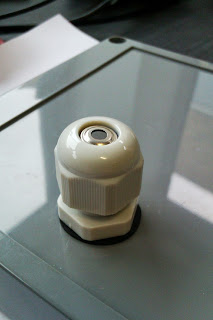
The new approach is to fit the sensor inside a cable gland. Before doing so I had to attach wires to the sensor connectors and insulate with heat-shrink sleeving. The result is shown below.


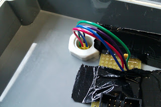
The next step is to fit the sensor in the cable gland before fitting the cable gland to the box.


The other end of the wires can then be soldered. For the prototype the wires are soldered to a small piece of stripboard. The stripboard has two pull-up resistors for the I2C bus and a decoupling capacitor. There is also an IDC connector to link the board to the unused JTAG interface. This was the easiest way to connect to a stock Calunium v2 board. For the lowest power operation the sensor is powered from logic-level output and I am using software I2C so all connections can be grounded when the sensor is not in use. The real-time clock on Calunium is connected the the hardware I2C interface on the microntroller and can be operated independently of the sensor.


The box and cable gland are rated IP65. Hopefully the result will be waterproof  

Results

The sensor is now deployed outside and reporting back to the Raspberry Pi base station. The transmitted packets are logged by the Raspberry Pi but as yet I don't have a convenient way to extract the ambient and object temperatures for analysis. That is the next task.


May
20

Cloud detector progress

AuroraWatchNet, Calunium, cloud detector, RaspberryPi, RFM12B Comments Off on Cloud detector progress 

Microcontroller and radio communications

To minimise the time and effort required to test the cloud detector concept I am following the approach used for the AuroraWatchNet magnetometer system and reusing as much hardware from it as possible. The MLX90614 non-contact infra-red temperature sensor is located outside. To minimise the infrastructure requirements the sensor unit is battery-powered and transmits its data over a bi-directional radio link. The sensor is controlled by one of my Calunium v2 microcontroller development boards. I'm using a pair of RFM12B radio modules operating at 433MHz to emulate a transparent serial connection. One is fitted on  the Calunium board and the other radio module is connected to a Raspberry Pi via my RFM12B shield. The Pi records the data and is responsible for uploading it for general access. I am also reusing most of the AuroraWatchNet firmware, which means I already have signed data communications and the capability to deploy over-the-air firmware updates - quite a good starting position for a new project!

Waterproofing the sensor

The biggest challenge I expect to face with this project is waterproofing the sensor. Although it is hermetically sealed there is no easy way to deploy it outside. As explained in a previous post, only a few materials are transparent to long-wave infra-red emissions and the better ones are toxic, water-soluble or expensive. I am therefore trying to avoid covering the sensor window and instead keep the electrical contacts dry. My first attempt was to drill a hole in the box and attach the sensor with silicone sealant. The mechanical fixing lacked strength and I wasn't convinced I had completely sealed around the sensor. To make matters worse I ended up with sealant on the sensor window which had to be cleaned off before it set. Another approach was required.

The new approach is to fit the sensor inside a cable gland. Before doing so I had to attach wires to the sensor connectors and insulate with heat-shrink sleeving. The result is shown below.


The next step is to fit the sensor in the cable gland before fitting the cable gland to the box.


The other end of the wires can then be soldered. For the prototype the wires are soldered to a small piece of stripboard. The stripboard has two pull-up resistors for the I2C bus and a decoupling capacitor. There is also an IDC connector to link the board to the unused JTAG interface. This was the easiest way to connect to a stock Calunium v2 board. For the lowest power operation the sensor is powered from logic-level output and I am using software I2C so all connections can be grounded when the sensor is not in use. The real-time clock on Calunium is connected the the hardware I2C interface on the microntroller and can be operated independently of the sensor.


The box and cable gland are rated IP65. Hopefully the result will be waterproof  

Results

The sensor is now deployed outside and reporting back to the Raspberry Pi base station. The transmitted packets are logged by the Raspberry Pi but as yet I don't have a convenient way to extract the ambient and object temperatures for analysis. That is the next task.


Mar
25

Des nouvelles de Bleuette

arduino, Bleuette, diy, hexapod, hexapode, planet, Raspberry, RaspberryPi, Robot, Robotique Comments Off on Des nouvelles de Bleuette 

Point presse

Tout d'abord, un point people, l'information du développement de Bleuette à plutôt bien circulée et Bleuette s'est retrouvée sur plusieurs sites importants :

La vidéo sur Vimeo à été vue plus de 6000 fois.

Plutôt plaisant de voir que ça intéresse du monde mais j'attends avec grande impatience le moment ou un autre Bleuette pointera le bout de son nez en PLA... ;)

Évolutions

Nouvelle carte fille

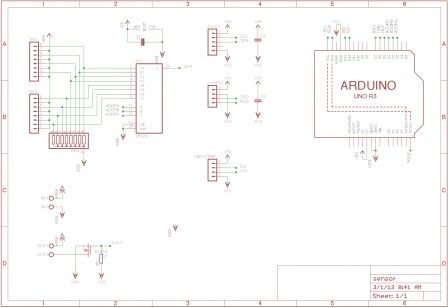
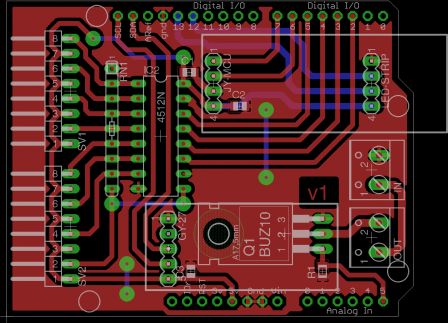
La shield Bleuette permet le pilotage des servos et le contrôle de la tension / courant consommé par les servos, pour pouvoir ajouter des capteurs multiples, il est tout à fait possible d'utiliser les broches libres des ports de l'Arduino mais il n'y en a pas assez pour tous les capteurs voulus sur Bleuette, du coup, le besoin d'une nouvelle carte d'extension s'est fait sentir et voici ce qu'elle permet :

  • 8 entrées supplémentaires multiplexées utilisant que 4 entrées / sorties (3 d'adressage et une sortie)
  • Connection pour une carte GY-27 contenant un accéléromètre et un compas
  • Un module Bluetooth JY-MCU
  • Une connection pour une guirlande de led RGB à base de LPD8806
  • Un mosfet pour pouvoir piloter un élément de puissance (je ne sais pas vraiment quoi pour le moment...)

Voici le schéma de principe et le PCB associé (cliquez dessus pour agrandir) :
Schéma de principe de la carte d'extension de Bleuette PCB de la carte d'extension de Bleuette

Le schéma de principe au format est Eagle se trouve par ici : sensor.sch et le PCB : sensor.brd

Comme vous pouvez le voir, le PCB n'est pas dense du tout, du coup, il est simple à réaliser avec des moyens modestes.

Mécanique

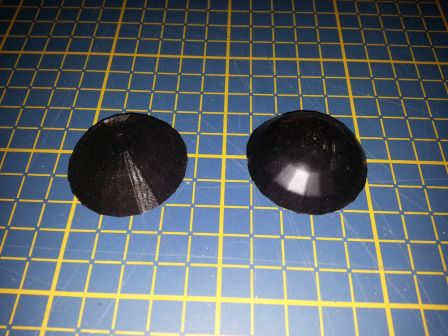
Pas de grande nouveauté pour la partie mécanique sauf pour les pieds, ces derniers ont été imprimés en PLA Flex permettant d'avoir un peu de souplesse et trempé dans du PlastiDip afin d'avoir un meilleur grip en plus d'un super rendu !

Avant trempage dans le PlastiDip et après :
Les pieds de Bleuette

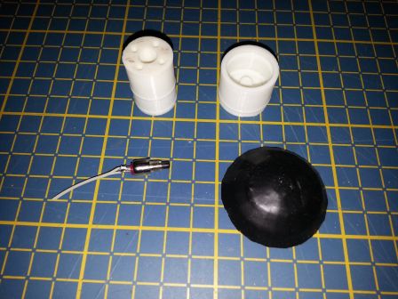
Tous les éléments d'un pied de Bleuette, on aperçoit l'interrupteur poussoir, le piston et le cylindre et le pied recouvert de PlastiDip :
L'ensemble des pièces constituant un pied de Bleuette

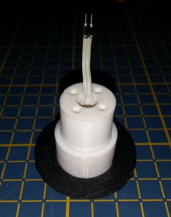
Le tout assemblé :
Vue d'un pied

Le fichier source au format OpenSCAD des pieds de Bleuette est disponible, comme tout le reste de Bleuette sur GitHub / Bleuette.

Le cerveau

J'ai subi beaucoup de soucis avec la carte Arduino, notamment des problèmes de programmation, m'obligeant à recommencer la phase 3-4 fois de suite des fois...
Tous ces ennuis m'ont conduit à radicalement changer ma manière de développer avec Arduino, notamment en utilisant Ino, un outils en ligne de commande pour compiler, programmer, etc, bref, un remplaçant du mal aimé environnement par défaut d'Arduino.

Les problèmes de liaison avec la carte Leonardo m'ont également conduit à une solution radicale, j'ai embarqué un Raspberry Pi dans Bleuette auquel est relié la carte Leonardo, ainsi, c'est le Raspberry Pi qui programme la carte Arduino, ça complique un peu mais au moins, je suis moins gêné...

À force d'utiliser ce système, ce qui devait arriver arriva et j'ai donc décidé de créer une carte fille pour le Raspberry Pi qui permettra de piloter Bleuette directement avec cette dernière.
Bien entendu, je ne laisse pas tomber pour autant le dèveloppement sur Arduino, disons que celui ci sera la version simplifiée.

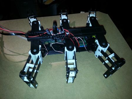
Bleuette embarquant un Raspberry Pi :
Bleuette embarquant un Raspberry Pi

D'ici peu, je publierai un article expliquant toutes les caractéristiques de la carte d'extension pour Raspberry Pi.

Muy buenas a todos otra vez. Hoy os traigo calentito el  3er capítulo de la serie “RaspberryPi Tutorials”. En este nuevo episodio tratamos el ecosistema entre dos de los más importantes dispositivos del mundo Open Source como son RaspberryPi y Arduino. Vamos a llevar a cabo una comunicación serie entre ambos dispositivos, veremos que archivos […]

Introduction

I previously showed an implementation of a AVR ISP programmer using the Raspberry Pi GPIO port which can be used to program Atmel's AVR range of microcontrollers with avrdude. An ISP programmer based on this design was incorporated into a shield to interface to the RFM12B radio module. This post explains how to use avrdude to actually program devices.

Software installation

Download the patched version of avrdude from http://project-downloads.drogon.net/files/. I also keep a copy in the RPi_RFM12B_ISP respository, https://github.com/stevemarple/RPi_RFM12B_ISP/tree/master/software/avrdude. You will probably want the armhf (hardware floating-point) version. Download the documentation package for avrdude too. Install the packages using "dpkg -i". For example

sudo dpkg -i avrdude_5.10-4_armhf.deb
sudo dpkg -i avrdude-doc_5.10-4_all.deb

Using avrdude over the GPIO interface is problematic for users other than root. The easiest solution is to give the avrdude binary setgroup permission:
sudo chmod g+s /usr/bin/avrdude

Usage

Selecting the GPIO programmer is simply a matter of including "-P gpio -c gpio" options; the -P option specifies that the GPIO port is used (as opposed to USB, serial or parallel interfaces) whilst the -c option selects the correct programmer type on that port.

For example, to check the signature on an ATmega328P execute the command
avrdude -P gpio -c gpio -p atmega328p

To read the fuses execute the command
avrdude -P gpio -c gpio -p atmega328 -U lfuse:r:-:h -U hfuse:r:-:h -U efuse:r:-:h

Customisation

The packages above define a single programmer called gpio which uses the gpio interface on GPIO pins 8 to 11. Since the RFM12B shield for Raspberry Pi implements two independent programmers I prefer to use gpio0 and gpio1. You can add these by creating a .avrduderc file in your home directory. The file should contain:

programmer
id = "gpio0";
desc = "Use sysfs interface to bitbang GPIO lines";
type = gpio;
reset = 8;
sck = 11;
mosi = 10;
miso = 9;
;

programmer
id = "gpio1";
desc = "Use sysfs interface to bitbang GPIO lines";
type = gpio;
reset = 7;
sck = 11;
mosi = 10;
miso = 9;
;

Mar
12

How to use the GPIO version of avrdude on the Raspberry Pi

arduino, RaspberryPi Comments Off on How to use the GPIO version of avrdude on the Raspberry Pi 

Introduction

I previously showed an implementation of a AVR ISP programmer using the Raspberry Pi GPIO port which can be used to program Atmel's AVR range of microcontrollers with avrdude. An ISP programmer based on this design was incorporated into a shield to interface to the RFM12B radio module. This post explains how to use avrdude to actually program devices.

Software installation

Download the patched version of avrdude from http://project-downloads.drogon.net/files/. I also keep a copy in the RPi_RFM12B_ISP respository, https://github.com/stevemarple/RPi_RFM12B_ISP/tree/master/software/avrdude. You will probably want the armhf (hardware floating-point) version. Download the documentation package for avrdude too. Install the packages using "dpkg -i". For example

sudo dpkg -i avrdude_5.10-4_armhf.deb
sudo dpkg -i avrdude-doc_5.10-4_all.deb

Using avrdude over the GPIO interface is problematic for users other than root. The easiest solution is to give the avrdude binary setgroup permission:
sudo chmod g+s /usr/bin/avrdude

Usage

Selecting the GPIO programmer is simply a matter of including "-P gpio -c gpio" options; the -P option specifies that the GPIO port is used (as opposed to USB, serial or parallel interfaces) whilst the -c option selects the correct programmer type on that port.

For example, to check the signature on an ATmega328P execute the command
avrdude -P gpio -c gpio -p atmega328p

To read the fuses execute the command
avrdude -P gpio -c gpio -p atmega328 -U lfuse:r:-:h -U hfuse:r:-:h -U efuse:r:-:h

Customisation

The packages above define a single programmer called gpio which uses the gpio interface on GPIO pins 8 to 11. Since the RFM12B shield for Raspberry Pi implements two independent programmers I prefer to use gpio0 and gpio1. You can add these by creating a .avrduderc file in your home directory. The file should contain:

programmer
id = "gpio0";
desc = "Use sysfs interface to bitbang GPIO lines";
type = gpio;
reset = 8;
sck = 11;
mosi = 10;
miso = 9;
;

programmer
id = "gpio1";
desc = "Use sysfs interface to bitbang GPIO lines";
type = gpio;
reset = 7;
sck = 11;
mosi = 10;
miso = 9;
;

Hola a tod@s de nuevo, hoy añadimos un nuevo capítulo más a la serie de videotutoriales “RaspberryPi tutorials”. Hoy os presento el capítulo 2, en el cual se intenta captar la atención de todos aquellos que quieran trabajar con su RaspberryPi como si fuese un Arduino. En este video os muestro como podéis instalaros las […]
Hola a tod@s, en esta nueva entrada os quiero presentar, así como inaugurar, está nueva serie de videtutoriales “RaspberryPi tutorials”, en la que, al igual que en “Arduino tutorials” y “Processing tutorials”, nos introduciremos en el mundo del minipc por excelencia del mundo Open Source. En este video os explico como grabar la tarjeta SD, [...]


  • Newsletter

    Sign up for the PlanetArduino Newsletter, which delivers the most popular articles via e-mail to your inbox every week. Just fill in the information below and submit.

  • Like Us on Facebook