11
Kit review – the Freetronics CUBE4: RGB LED Cube
4x4x4, arduino, argot, cube, freetronics, jaycar, kit, kit review, LED, leonardo, LeoStick, review, RGB, XC4274 Comments Off on Kit review – the Freetronics CUBE4: RGB LED Cube
Introduction
LED cubes are a fascinating item, no matter where you come from the allure of blinking LEDs in various patterns is always attractive. And making your own is a fun challenge that most people can do after some experience with electronics hardware. However most people use single-colour LEDs, as wiring up RGB units triples the complexity of the circuit. Until now.
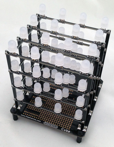
After much anticipation Freetronics have released their CUBE4 RGB LED cube kit – a simple to assemble and completely-customisable RGB LED cube:

Unlike other cubes on the market, this one includes an on-board ATmega32u4 microcontroller with Arduino Leonardo-compatible bootloader and a microUSB socket (… and a lot more) – so you don’t need anything extra to get started. And this gives you many more options when you’re ready to expand. But first let’s put it together and then get it working. Furthermore, keep reading to find out how you can have a chance to win your own Cube4.
Assembly
Inside the box are all the parts needed for the kit, even a microUSB cable to power the Cube4 and also communicate with it:

There’s 64 RGB LEDs in that bag, so get ready for some soldering. The base PCB is well laid out, labelled and gives you an idea for the expansion possibilities:

Plenty of room to add your own circuitry – and the bottom:

As you can see in the image above, there’s an XBee-compatible pinout if you want to add communication via wirless serial link, plenty of prototyping space for your own additions and many other ports are brought out to open pads. There’s even a 5V supply pair to test LEDs, and a blue “power on” LED (which can be deactivated if necessary by cutting a track on the PCB).
The first job is to mount the LEDs on their plane PCBs – there are four, one for each horizontal plant. It’s very important to get the LEDs in the right way round, and there’s markers on the PCB that you can match up the longest leg of the LED with:

From experience I found it best to insert all the LEDs:

…and then do a final mass check of the alignment – which is easy if you hold the plane up to one side and compare the legs, for example:

At this stage it’s a great idea to double-check your LED alignment. After a while you’ll have the LEDs soldered in and trimmed nicely:

The next step was getting the vertical sticks aligned in order to hold the LED planes (above). Each stick is for a particular spot on the PCB so check the label on the stick matches the hole on the PCB. It’s incredibly important to make sure you have them perfectly perpendicular to the PCB, so find something like a square-edge or card to help out:

Once you have a row of sticks in you can start with a plane then insert a stick on the other side, for example:

Note the use of the elastic band to hold things together – they really help. Then it’s a simple matter of adding the planes and holding it together with another band:

… at which point you can do a final check that all the planes and sticks are inserted correctly. Then solder all the copper spots together and you’re done.
Don’t forget to turn the cube upside-down as there’s soldering to be done on the bottom of the planes as well:

Although it might look a little scary, the final assembly isn’t that difficult – just take your time so it’s right the first time. You can view the following video which describes the entire process:
Once you’re confident that all the soldering has been completed – double-check for joints that aren’t completely bridged with solder as they will affect the operation of the cube. Then you can plug in the USB cable and watch the preloaded test/demonstration sketch in action:
If all your LEDs are working, awesome. If not – check the soldering. If there’s still some rogues – check your individual LEDs. Some of you are probably thinking “well that isn’t too colourful” – the problem is the camera, not the Cube4. If you see it in real life, it’s much better.
Operation
There are two methods of controlling the Cube4. It is delivered with a preloaded sketch that runs the demonstration showed in the video above, and then accepts commands over a serial/USB connection. So you can simply plug it in, fire up a terminal program (or the Arduino IDE serial monitor) and send text commands to do various things. If you type “help ;” the syntax is returned which explains how you can do things (click image to enlarge):

This serial control mode allows control by any type of software that can write to a serial port. Furthermore any other external hardware that can create or introduce serial text can also control the Cube4. For example by mounting an XBee module underneath and linking it to the TX/RX lines gives you a wireless Cube4. By doing so you can control it with a Raspberry Pi or other system.
Furthermore the Cube4 is also an Arduino Leonardo-compatible board in the same way as a Freetronics LeoStick. With the use of the Cube4 Arduino library you can then create your own sketches which can visualise data with very simple to use functions for the Cube4. There are some great example sketches with the library for some inspiration and fun. Over time I look forward to using the Cube4 in various ways, including adding an Electric Imp IoT device and making another clock (!).
Competition
Would you like the chance to win a Cube4? It’s easy. Clearly print your email address on a postcard, and mail it to:
CUBE4 Competition, PO Box 5435, Clayton 3168, Australia
Entries must be received by the 30th of July 2013. One postcard will then be drawn at random, and the winner will receive one Cube4 delivered by Australia Post standard air mail. You can enter as many times as you like. We’re not responsible for customs or import duties, VAT, GST, postage delays, non-delivery or whatever walls your country puts up against receiving inbound mail.
More demonstrations
Check out this Argot IoT demonstration.
Conclusion
This is the most approachable RGB LED cube kit on the market, and also the easiest to use. You don’t need to understand programming to try it out – and if you do it’s incredibly versatile. A lot of work has gone into the library, API and hardware design so you’ve got an expandable tool and not just some blinking LEDs. For more information visit the Freetronics website. Larger photos available on flickr. And if you made it this far – check out my new book “Arduino Workshop” from No Starch Press.

The CUBE4 in this review is a promotional consideration from Freetronics. In the meanwhile have fun and keep checking into tronixstuff.com. Why not follow things on twitter, Google+, subscribe for email updates or RSS using the links on the right-hand column? And join our friendly Google Group – dedicated to the projects and related items on this website. Sign up – it’s free, helpful to each other – and we can all learn something.