Posts | Comments

Planet Arduino

Archive for the ‘december’ Category

Nov
10

Introduction

In this review of an older kit (circa 1993~1997) we examine the Diesel Sound Simulator for Model Railroads kit from (the now defunct) Dick Smith Electronics, based on the article published in the December 1992 issue of Silicon Chip magazine.

The purpose of this kit is to give you a small circuit which can fit in a HO scale (or larger) locomotive, or hidden underneath the layout – that can emulate the rumbling of a diesel-electric locomotive to increase the realism of a train. However the kit is designed for use with a PWM train controller (also devised by Silicon Chip!) so not for the simple direct-DC drive layouts.

K3030 diesel sound simulator kit

Assembly

The diesel sound kit was from the time when DSE still cared about kits, so you received the sixteen page “Guide to Kit Construction” plus the kit instructions, nasty red disclaimer sheet, feedback card, plus all the required components and the obligatory coil of solder that was usually rubbish:

K3030 diesel sound simulator kit contents

Everything required to get going is included, except IC sockets. My theory is it’s cheaper to use your own sockets than source older CMOS/TTL later on if you want to reuse the ICs, so sockets are now mandatory here:

K3030 diesel sound simulator kit parts

The PCB is from the old school of “figure-it-out-yourself”, no fancy silk-screening here:

K3030 diesel sound simulator kit PCB

K3030 diesel sound simulator kit PCB bottom

Notice the five horizontal pads between the two ICs – these were for wire bridges in case you needed to break the PCB in two to fit inside your locomotive.

Actual assembly was straight-forward, all the components went in without any issues. Having two links under IC2 was a little annoying, however a short while later the PCB was finished and the speaker attached:

K3030 diesel sound simulator kit finished

How it works

As mentioned earlier this diesel sound kit was designed for use with the Silicon Chip train PWM controller, so the design is a little different than expected. It can handle a voltage of around 20 V, and the sound is determined by the speed of the locomotive.

The speed is determined by the back EMF measured from the motor – and (from the manual) this is the voltage produced by the motor which opposes the current flow through it and this voltage is directly proportional to speed.

Not having a 20V DC PWM supply laying about I knocked up an Arduino to PWM a 20V DC supply via an N-MOSFET module and experimented with the duty cycle to see what sort of noises could be possible. The output was affected somewhat by the supply voltage, however seemed a little higher in pitch than expected.

You can listen to the results in the following video:

I reckon the sound from around the twenty second mark isn’t a bad idle noise, however in general not that great. The results will ultimately be a function of a lower duty-cycle than I could create at the time and the values of R1 and R2 used in the kit.

 Conclusion

Another kit review over. With some time spent experimenting you could generate the required diesel sounds, a Paxman-Valenta it isn’t… but it was a fun kit and I’m sure it was well-received at the time. To those who have been asking me privately, no I don’t have a secret line to some underground warehouse of old kits – just keep an eye out on ebay and they pop up now and again. Full-sized images and much more information about the kit are available on flickr.

And while you’re here – are you interested in Arduino? Check out my new book “Arduino Workshop” from No Starch Press.

In the meanwhile have fun and keep checking into tronixstuff.com. Why not follow things on twitterGoogle+, subscribe  for email updates or RSS using the links on the right-hand column? And join our friendly Google Group – dedicated to the projects and related items on this website. Sign up – it’s free, helpful to each other –  and we can all learn something.

The post Old Kit Review – Diesel Sound Simulator for Model Railroads appeared first on tronixstuff.

Introduction

Every month Australian electronics magazine Silicon Chip publishes a variety of projects, and in December 2012 they published the USB Power Monitor by Nicholas Vinen. Jaycar picked it up and now offers a kit, the subject of our review. This small device plugs inline between a USB port and another device, and can display the current drawn, power and voltage at the USB port with a large LCD module. This is useful when you’re experimenting with USB-powered devices such as Arduino projects or curious how external USB devices can affect your notebook computer’s battery drain.

Assembly

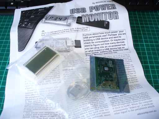
The kit arrives in typical Jaycar fashion:

… everything necessary is included with the kit:

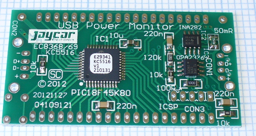
The instructions arrive as an updated reprint of the original magazine article, plus the usual notes from Jaycar about warranty and their component ID sheet which is useful for beginners. The PCB is quite small, and designed to be around the same size as the LCD module:

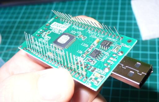
As you can see below, most of the work is already done due to the almost exclusive use of SMD components:

That’s a good thing if you’re in a hurry (or not the best with surface-mount work). Therefore the small amount of work requires is simply to solder in the USB sockets, the button and the LCD:

It took less than ten minutes to solder together. However – take careful, careful note of the LCD. There isn’t a pin 1 indicator on the module – so instead hold the LCD up to the light and determine which side of the screen has the decimal points – and line it up matching the silk-screening on the PCB. Once finished you can add the clear heatshrink to protect the meter, but remember to cut a small window at the back if you want access to the ICSP pins for the PIC microcontroller:

How it works

The USB current is passed through a 50 mΩ shunt resistor, with the voltage drop being measured by an INA282 current shunt monitor IC. The signal from there is amplified by an op amp and then fed to the ADC of a PIC18F45K80 microcontroller, which does the calculations and drives the LCD. For complete details purchase the kit or a copy of the December 2012 edition of Silicon Chip.

Operation

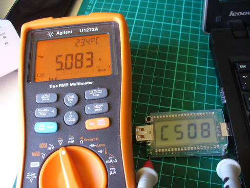
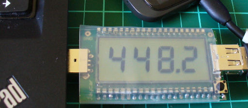
First you need to calibrate the unit – when first used the meter defaults to calibration mode. You simply insert it into a USB port. then measure the USB DC voltage brought out to two pads on the meter. By pressing the button you can match the measured voltage against the display as shown below – then you’re done.

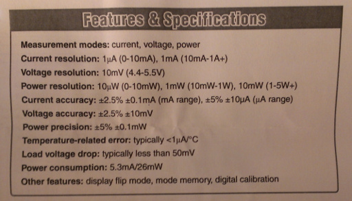
Then you simply plug it in between your USB device and the socket. Press the button to change the measurement. The meter can measure the following ranges:

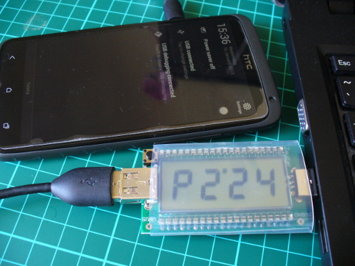
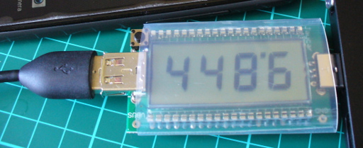
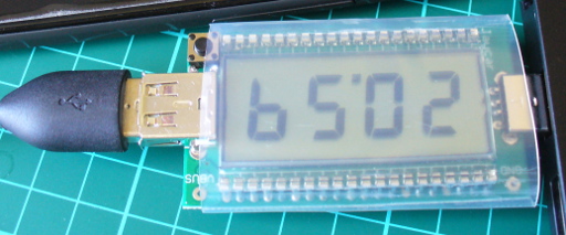
For an operational example. consider the next three images are from charging my phone – with the power, current and voltage being shown:

“P” for power…

current in mA

“b” for bus voltage

If you want to use the USB ports on the right-hand side of your computer, just press the button while inserting the meter – and it flips around:

Finally – here’s a quick video of the meter at work, whilst copying a file to an external USB hard drive:

Conclusion

I really like this – it’s simple and it works. Kudos to Nicholas for his project. You can purchase it from Jaycar and their resellers, or read more about it in the December 2012 edition of Silicon Chip. Full-sized images available on flickr. This kit was purchased without notifying the supplier.

In the meanwhile have fun and keep checking into tronixstuff.com. Why not follow things on twitterGoogle+, subscribe  for email updates or RSS using the links on the right-hand column? And join our friendly Google Group – dedicated to the projects and related items on this website. Sign up – it’s free, helpful to each other –  and we can all learn something.

The post Kit Review – SC/Jaycar USB Power Monitor appeared first on tronixstuff.


  • Newsletter

    Sign up for the PlanetArduino Newsletter, which delivers the most popular articles via e-mail to your inbox every week. Just fill in the information below and submit.

  • Like Us on Facebook