Posts | Comments

Planet Arduino

Archive for the ‘ldr’ Category

Mar
30

Simple technique of sensing colors using Arduino

arduino, ldr, LED, OLED, RGB Comments Off on Simple technique of sensing colors using Arduino 

dsc07095

ZXLee built a simple sensor for Arduino which allows him to detect colors. The idea lies behind using red, green, blue LEDs and Light Dependent Resistor (LDR). Lee Zhi Xian writes:

Previously I have made a colour sensor using Arduino but don’t have the time to update it on my blog. Today I am going to share the details of this mini project. Basically, the sensor consists of three LEDs and Light Dependent Resistor (LDR). The LDR will detect the colour and display it to another RGB LED. Besides display it on the RGB LED, the colour will also display on PC. RGB LED is commonly used in display colours on LCD or OLED such as the monitor and television.

[via]

Simple technique of sensing colors using Arduino - [Link]

Feb
25

Using a flashing LCD monitor to transfer data

arduino hacks, data transfer, flashing, ldr, light sensor, monitor, screen, temt6000 Comments Off on Using a flashing LCD monitor to transfer data 

lcd-screen-data-transferWe love the concept of using an LCD screen to transfer data. The most wide-spread and successful method we know of is the combination of a QR code and the camera on a smart phone. But for less powerful/costly devices data can be transferred simply by flashing colors on the screen. That’s what [Connor Taylor] is testing out with this project. He’s using a TEMT6000 light sensor to turn a white and black flashing monitor into binary data.

So far this is just a proof of concept that takes measurements from the light sensor which is held in front of a Macbook Retina display with different backlight levels. At 3/4 and full brightness it provides more than enough contrast to reliably differentiate between black and white when measuring the sensor with the Arduino’s ADC. What he hasn’t gotten into yet is the timing necessary to actually transfer data. The issue arises when you need to have multiple 1′s or 0′s in a row. We’ve tried this ourselves using an LDR with limited success. We know it’s possible to get it working since we’ve seen projects like this clock which can only be programmed with a flashing screen.

[Connor's] choice of the TEMT6000 should prove to be a lot more sensitive than using just an LDR. We figure he could find a way to encode using multiple colors in order to speed up the data transfer.


Filed under: arduino hacks
Jan
18

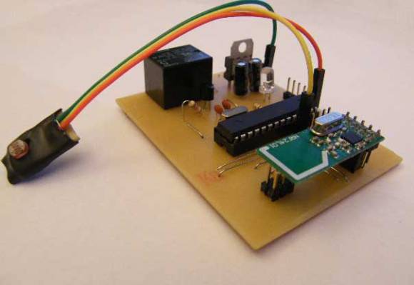
Humble beginnings of a home automation project

arduino hacks, Home automation, ldr, milling, pcb, Relay Comments Off on Humble beginnings of a home automation project 

humble-beginnings-to-a-home-automation-project

This board is the start of [Steven Pearson's] quest to automate his home. The module will be used to prototype the rest of the project. Right now it uses an ATmega328 chip running the Arduino bootloader. This connects to one mechanical relay which we would wager is mains rated. The module will be controlled wirelessly via the wireless module seen in the foreground. That is a nRF24L01 board which he chose because of it’s bargain basement price tag of around $1.50.

There is much room for expansion in the system. You can see that a light-dependent resistor has been added to some of the microcontroller’s breakout pins. We would guess that [Steven] will use the hardware to develop for many different functions and will design more task-specific modules as the project progresses.

If you’re a fan of PCB milling and population you won’t want to miss the video after the break. [Steve] posted a fast-motion video of the entire process.


Filed under: arduino hacks
Nov
23

Simple Light Reading With LDR + Arduino

arduino, ldr, light, tutorials Comments Off on Simple Light Reading With LDR + Arduino 

The LDR (light dependent resistor) also know as the Photo-resistor (and many other things) is supposed to be day 1 of electronics. But I guess I missed the note because I never used one with my arduino maybe until now. So I guess I’m weird. But the LDR is super cheap, probably one of the easiest parts to find / use, and certainly has to have the simplest code. You can find these at any electronics store ever I imagine, or do what I did and add a few to your next sparkfun order.

If you need precise light measurement check out the TEMT6000 or the TSL230R

The LDR / Photo-resistor is basically a very simple light sensor that changes its resistance with light, lowering with more light. You can find these used in everything from the furby to automatic night lights and things like that. The LDR isn’t very precise, so you cant get a quantitative LUX reading or anything like that. But it is good enough to tell the difference between light and shadow, or know if the light in your room is on/off. So if you just need to know if the light in the room has changed, or someone walked by (casting a shadow) this is your part.

Hooking it up, and why

The LDR changes its resistance with light so we can measure that change using one of the Arduino’s analog pins. But to do that we need a fixed resistor (not changing) that we can use for that comparison (We are using a 10K resistor). This is called a voltage divider and divides the 5v between the LDR and the resistor. Then we measure how much voltage is on the LDR using the analog read on your arduino, and we have our reading. The amount of that 5V that each part gets is proportional to its resistance.

With the arduino analogRead, at 5V (its max) it would read 1023, and at 0v it read 0.

So if the the LDR and the resistor have the same resistance, the 5V is split evenly (2.5V), to each part. (analogRead of 512)

But if the LDR is hit with a ton of light and is reading only 1K of resistance, the 10K resistor is going to soak up 10 times as much of that 5V. So the LDR would only get .45V (analogRead of 92).

And if it is in a dark room, the LDR may be 40K or resistance, so the LDR will soak up 4 times as much of that 5V as the 10K resistor. So the LDR would get 4V (analogRead of 818).

Code

The arduino code for this just could not be easier. We are adding some serial prints and delays to it just so you can easily see the readings, but they dont need to be there if you dont need them.

int LDR_Pin = A0; //analog pin 0

void setup(){
  Serial.begin(9600);
}

void loop(){
  int LDRReading = analogRead(LDR_Pin); 

  Serial.println(LDRReading);
  delay(250); //just here to slow down the output for easier reading
}
Unless otherwise stated, this code is released under the MIT License – Please use, change and share it.

On my last post I introduced the IPON project, and today I’m sharing the implementation of Phase 0 of this project. (You may want to refer to the previous post if you haven’t yet read it, as this post will probably make much more sense if you know what the IPON project is about). In […]

The post Phase 0 of the IPON Project appeared first on Tinker Hobby.

I have recently received the following question from a reader: I’m looking for a circuit board design that will need to turn on an array of LEDs when motion is detected during the day time, and also stay on continuously during the night time; using the Arduino would be nice. The project that I am […]

The post Motion and Light Sensors with Arduino (and Without) appeared first on Tinker Hobby.


  • Newsletter

    Sign up for the PlanetArduino Newsletter, which delivers the most popular articles via e-mail to your inbox every week. Just fill in the information below and submit.

  • Like Us on Facebook