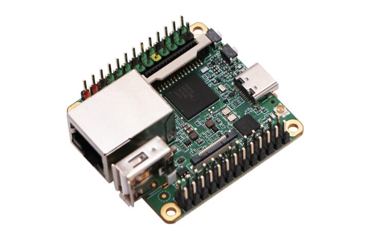
Shenzhen MilkV Technology’s Duo S is a tiny SBC based on the 1 GHz Sophgo SG2000 Arm Cortex-A53 and RISC-V SoC with 512MB DDR3 (SiP), Fast Ethernet, WiFi 6, and Bluetooth 5 connectivity, and a switch to select Arm or RISC-V architecture before powering the board. We already had covered SG2002 Arm/RISC-V boards with 256MB RAM, namely the LicheeRV Nano and Duo 256M, but for people needing more memory, the Duo S provides another option that also features two 2-lane MIPI CSI connectors, a USB 2.0 host port, and two 26-pin headers for expansion. Its form factor reminds me of FriendlyELEC’s NanoPi NEO and family powered by Allwinner processors that were introduced a few years ago. Duo S specifications: SoC – SOPHGO SG2000 Main core – 1 GHz 64-bit RISC-V C906 or Arm Cortex-A53 core (selectable) Minor core – 700 MHz 64-bit RISC-V C906 core Low-power core – 25 to [...]
Today, anyone can shoot video because cameras are cheap and readily available. But if you want to do fancy Hollywood-style moving shots, you’ll need somebody to point the thing — or a machine to do it for you. [Giovanni Aggiustatutto] went the latter route with this mechanized pan-tilt build.
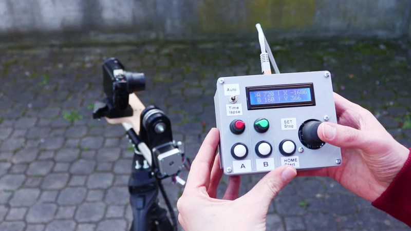
The build relies on stepper motors for clean and accurate movement on both axes. Belt drives are used to step down the output of the motors for greater torque. The pan-tilt mechanism itself is built from a combination of 3D printed parts paired with wooden components and a pair of aluminium tubes for rigidity. The whole assembly comes with a standard mount for use with a regular tripod. An Arduino Uno runs the show, using TMC2208 stepper drivers to command the motors. A control pad featuring a joystick and buttons is used for control, with an LCD to provide useful feedback to the user.
If you’re interested in embedded machine learning (TinyML) on the Arduino Nano 33 BLE Sense, you’ll have found a ton of on-board sensors — digital microphone, accelerometer, gyro, magnetometer, light, proximity, temperature, humidity and color — but realized that for vision you need to attach an external camera.
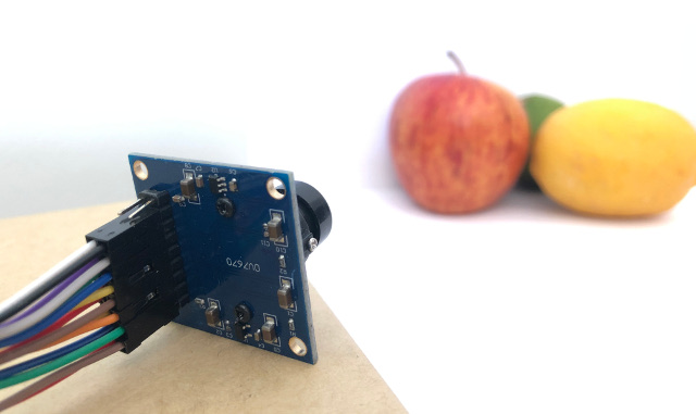
In this article, we will show you how to get image data from a low-cost VGA camera module. We’ll be using the Arduino_OVD767x library to make the software side of things simpler.
You can of course get a board without headers and solder instead, if that’s your preference.
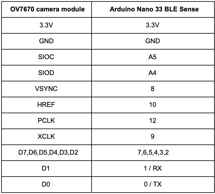
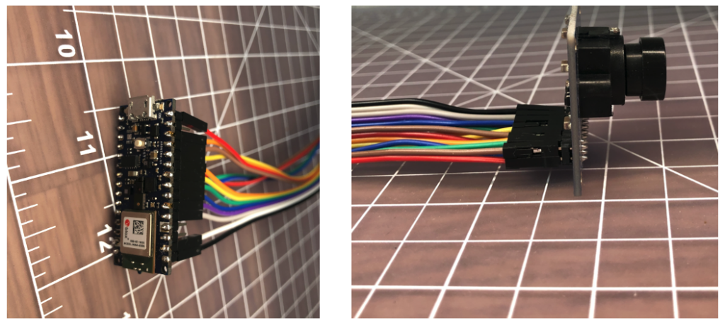
The one downside to this setup is that (in module form) there are a lot of jumpers to connect. It’s not hard but you need to take care to connect the right cables at either end. You can use tape to secure the wires once things are done, lest one comes loose.
You need to connect the wires as follows:
Software setup
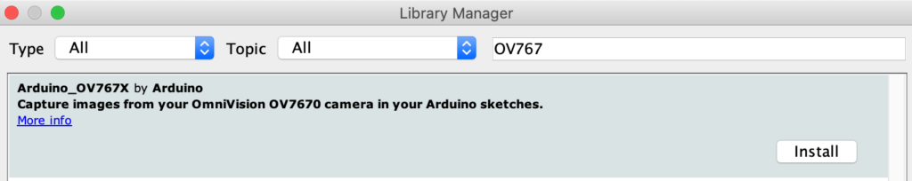
First, install the Arduino IDE or register for Arduino Create tools. Once you install and open your environment, the camera library is available in the library manager.
Tools > Manage Libraries and search for the OV767 library
Press the Install button
Now, we will use the example sketch to test the cables are connected correctly:
Examples > Arduino_OV767X > CameraCaptureRawBytes
Uncomment line 48 to display a test pattern – Camera.testPattern();
Compiler and upload to your board
Your Arduino is now outputting raw image binary over serial. You cannot view the image using the Arduino Serial Monitor; instead, we’ve included a special application to view the image output from the camera using Processing.
Processing is a simple programming environment that was created by graduate students at MIT Media Lab to make it easier to develop visually oriented applications with an emphasis on animation and providing users with instant feedback through interaction.
Open Examples > Arduino_OV767X > extras > CameraVisualizerRawBytes
Copy the CameraVisualizerRawBytes code
Paste the code into the empty sketch in Processing
Edit line 35-37 to match the machine and serial port your Arduino is connected to
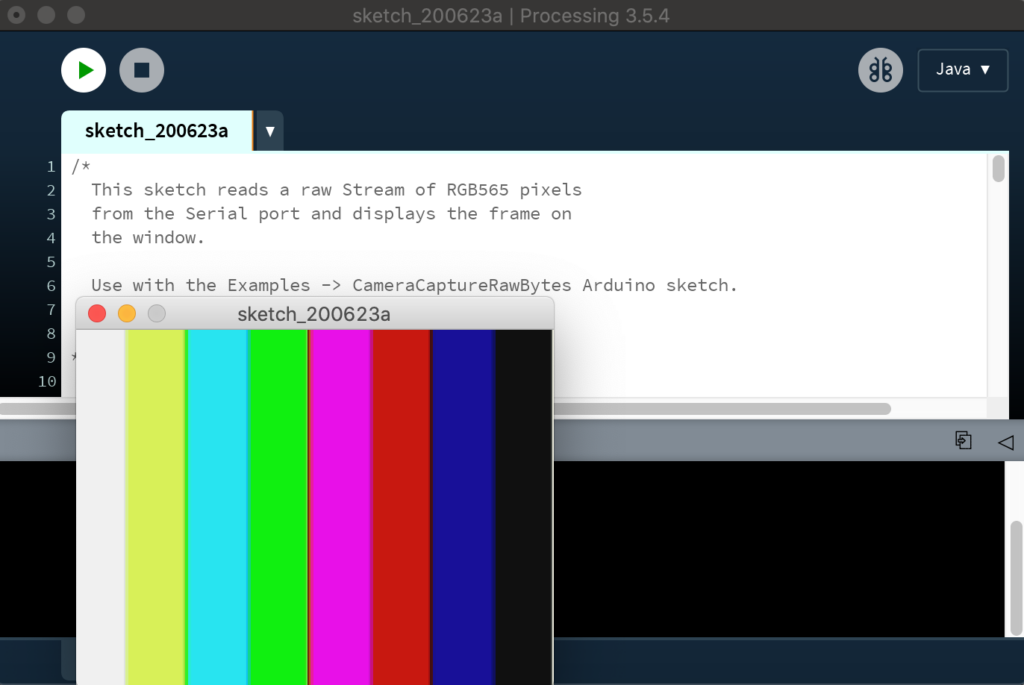
Hit the play button in Processing and you should see a test pattern (image update takes a couple of seconds):
If all goes well, you should see the striped test pattern above! To see a live image from the camera in the Processing viewer:
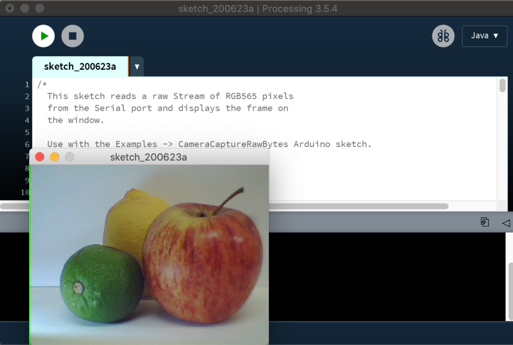
If you now comment out line 48 of the Arduino sketch
Compile and upload to the board
Once the sketch is uploaded hit the play button in Processing again
After a few seconds you should now have a live image:
Considerations for TinyML
The full VGA (640×480 resolution) output from our little camera is way too big for current TinyML applications. uTensor runs handwriting detection with MNIST that uses 28×28 images. The person detection example in the TensorFlow Lite for Microcontrollers example uses 96×96 which is more than enough. Even state-of-the-art ‘Big ML’ applications often only use 320×320 images (see the TinyML book). Also consider an 8-bit grayscale VGA image occupies 300KB uncompressed and the Nano 33 BLE Sense has 256KB of RAM. We have to do something to reduce the image size!
Camera format options
The OV7670 module supports lower resolutions through configuration options. The options modify the image data before it reaches the Arduino. The configurations currently available via the library today are:
VGA – 640 x 480
CIF – 352 x 240
QVGA – 320 x 240
QCIF – 176 x 144
This is a good start as it reduces the amount of time it takes to send an image from the camera to the Arduino. It reduces the size of the image data array required in your Arduino sketch as well. You select the resolution by changing the value in Camera.begin. Don’t forget to change the size of your array too.
Camera.begin(QVGA, RGB565, 1)
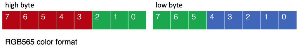
The camera library also offers different color formats: YUV422, RGB444 and RGB565. These define how the color values are encoded and all occupy 2 bytes per pixel in our image data. We’re using the RGB565 format which has 5 bits for red, 6 bits for green, and 5 bits for blue:
Converting the 2-byte RGB565 pixel to individual red, green, and blue values in your sketch can be accomplished as follows:
    // Convert from RGB565 to 24-bit RGB

    uint16_t pixel = (high << 8) | low;

    int red   = ((pixel >> 11) & 0x1f) << 3;
    int green = ((pixel >> 5) & 0x3f) << 2;
    int blue  = ((pixel >> 0) & 0x1f) << 3;
Resizing the image on the Arduino
Once we get our image data onto the Arduino, we can then reduce the size of the image further. Just removing pixels will give us a jagged (aliased) image. To do this more smoothly, we need a downsampling algorithm that can interpolate pixel values and use them to create a smaller image.
The techniques used to resample images is an interesting topic in itself. We found the simple downsampling example from Eloquent Arduino works with fine the Arduino_OV767X camera library output (see animated GIF above).
Applications like the TensorFlow Lite Micro Person Detection example that use CNN based models on Arduino for machine vision may not need any further preprocessing of the image — other than averaging the RGB values in order to remove color for 8-bit grayscale data per pixel.
However, if you do want to perform normalization, iterating across pixels using the Arduino max and min functions is a convenient way to obtain the upper and lower bounds of input pixel values. You can then use map to scale the output pixel values to a 0-255 range.
This was an introduction to how to connect an OV7670 camera module to the Arduino Nano 33 BLE Sense and some considerations for obtaining data from the camera for TinyML applications. There’s a lot more to explore on the topic of machine vision on Arduino — this is just a start!
Just a few years ago, had someone asked you how much a digital camera with WiFi would cost, you probably wouldn’t have said $6. But that’s about how much [Bitluni] paid for an ESP32-CAM. He wanted to try making the little camera do time lapse, and it turns out that’s pretty easy to do.
Of course, the devil is in the details. The camera starts out needing configuration on the USB interface and that enables the set up of Arduino integration and WiFi configuration. Because it stores each frame of the image on an SD card, the board can’t take rapid-fire pictures. [Bitluni] reports a 3-second delay was about the shortest he could manage, but for most purposes, he was using at least ten seconds.
The program has a live preview window to help you set up the shot, but before you recordings start that should be turned off so as not to overload the little processor and the I/O busses. The result is a bunch of JPG images that you can easily convert that to a video on a PC if you wish.
This might be a good way to fit a camera on a 3D printer, especially if the time lapse effect was desired. Otherwise, you might sync to a layer change. Now all [bitluni] needs is an orbital rig.
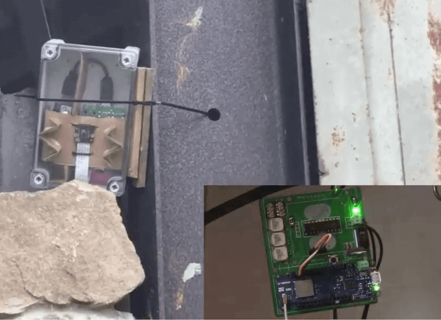
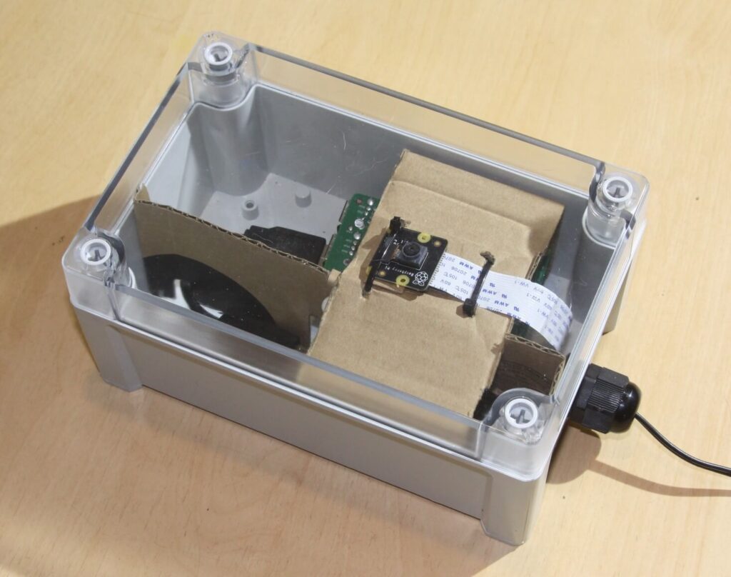
Security cameras are a great way to deter theft and vandalism, but what if the camera is out of WiFi range, or otherwise would need long cables to transmit pictures? As explained here, Tegwyn Twmffat has an interesting solution–taking advantage of neural network processing to recognize moving objects, along with a LoRa connection to sound the alarm when there is a potential problem.
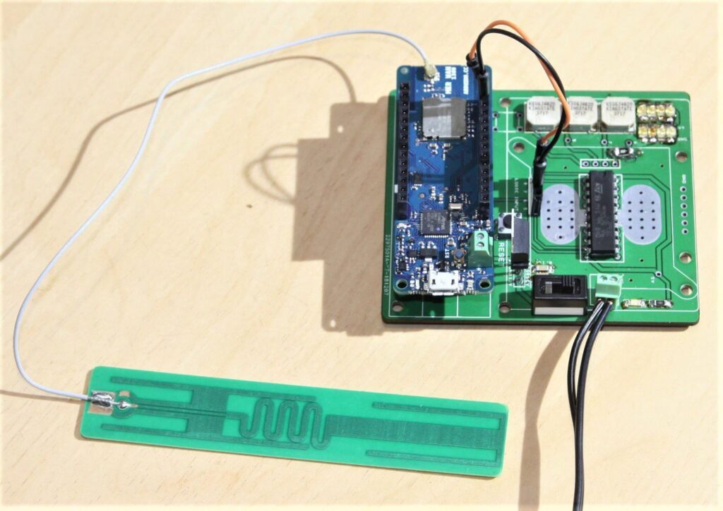
Images are captured by a Raspberry Pi and camera, then processed with the help of an Intel Movidius Neural Compute Stick for identification. If it’s something of interest—a human, for example—a relatively small amount of data is transmitted to a MKR WAN 1300 base station, beeping faster and faster as the person approaches.
As seen in the video below, it’s able to properly ignore the ‘test dog,’ while it beeps away when a person approaches!
[JBumstead] didn’t want an ordinary microscope. He wanted one that would show the big picture, and not just in a euphemistic sense, either. The problem though is one of resolution. The higher the resolution in an image — typically — the narrower the field of view given the same optics, which makes sense, right? The more you zoom in, the less area you can see. His solution was to create a microscope using a conventional camera and building a motion stage that would capture multiple high-resolution photographs. Then the multiple photos are stitched together into a single image. This allows his microscope to take a picture of a 90x60mm area with a resolution of about 15 μm. In theory, the resolution might be as good as 2 μm, but it is hard to measure the resolution accurately at that scale.
As an Arduino project, this isn’t that difficult. It’s akin to a plotter or an XY table for a 3D printer — just some stepper motors and linear motion hardware. However, the base needs to be very stable. We learned a lot about the optics side, though.
Two Nikon lenses and an aperture stop made from black posterboard formed a credible 3X magnification element. We also learned about numerical aperture and its relationship to depth of field.
One place the project could improve is in the software department. Once you’ve taken a slew of images, they need to blend together. It can be done manually, of course, but that’s no fun. There’s also a MATLAB script that attempts to automatically stitch the images together, blending the edges together. According to the author, the code needs some work to be totally reliable. There are also off-the-shelf stitching solutions, which might work better.
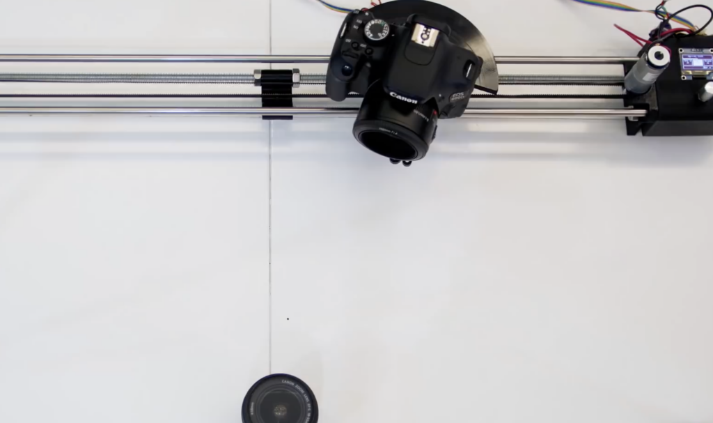
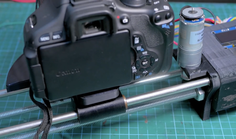
When filming your projects—or day-to-day life—static shots can be fun, but having a moving perspective often looks even better. The challenge is keeping the camera pointed at your subject, which maker Saral Tayal addresses with his automated slider.
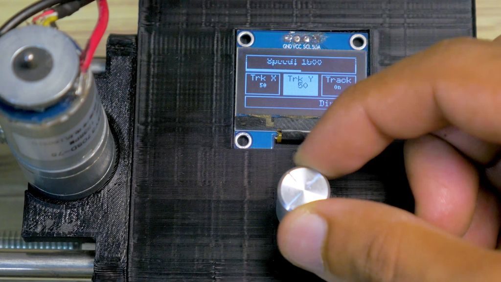
This Arduino Uno-controlled slider is powered by a pair of brushed DC motors with encoders attached for feedback. One pulls the camera along a pair of rails on a set of linear bearings, while the other adjusts the camera’s horizontal angle using trigonometry to keep a particular object in-frame.
Code and print files are available in Tayal’s write-up, and some beautiful resulting shots with an explanation of the project can be seen in the video below.
A Raspberry Pi with a camera is nothing new. But the Pixy2 camera can interface with a variety of microcontrollers and has enough smarts to detect objects, follow lines, or even read barcodes without help from the host computer. [DroneBot Workshop] has a review of the device and he’s very enthused about the camera. You can see the video below.
When you watch the video, you might wonder how much this camera will cost. Turns out it is about $60 which isn’t cheap but for the capabilities it offers it isn’t that much, either. The camera can detect lines, intersections, and barcodes plus any objects you want to train it to recognize. The camera also sports its own light source and dual servo motor drive meant for a pan and tilt mounting arrangement.
You can connect via USB, serial, SPI, or I2C. Internally, the camera processes at 60 frames per second and it can remember seven signatures internally. There’s a PC-based configuration program that will run on Windows, Mac, or Linux. You can even use the program to spy on the camera while it is talking to another microcontroller like an Arduino.
The camera isn’t made to take sharp photos or video, but it is optimized for finding things, not for picture quality. High-quality frames take more processing power, so this is a reasonable trade. The camera does need training to find objects by color and shape. You can do the training with the PC-based software, but you can also do it with a self-contained procedure that relies on a button on the camera. The video shows both methods.
Once trained, you can even have an Arduino find objects. There’s a library that allows you to find how many items the camera currently sees and find out what the block is and its location. The identification clearly depends highly on color, so you’ll probably need to experiment if you have things that are different colors on different sides or has multiple colors.
Sure, you could use a sufficient computer with OpenCV to get some of these results, but having this all in one package and usable from just about any processor could be a real game-changer for the right kind of project. If you wanted to make a fancy line-following robot that could handle 5-way intersections and barcode commands this would be a no-brainer.
We’ve seen other smart cameras like OpenMV before. Google also has a vision processor for the Pi, too. It has a lot of capability but assumes you are connecting to a Pi.
When you think of image processing, you probably don’t think of the Arduino. [Jan Gromes] did, though. Using a camera and an Arduino Mega, [Jan] was able to decode input from an Arduino-connected camera into raw image data. We aren’t sure about [Jan’s] use case, but we can think of lots of reasons you might want to know what is hiding inside a compressed JPEG from the camera.
The Mega is key, because–as you might expect–you need plenty of memory to deal with photos. There is also an SD card for auxiliary storage. The camera code is straightforward and saves the image to the SD card. The interesting part is the decoding.
The use case mentioned in the post is sending image data across a potentially lossy communication channel. Because JPEG is compressed in a lossy way, losing some part of a JPEG will likely render it useless. But sending raw image data means that lost or wrong data will just cause visual artifacts (think snow on an old TV screen) and your brain is pretty good at interpreting lossy images like that.
Just to test that theory, we took one of [Joe Kim’s] illustrations, saved it as a JPEG and corrupted just a few bytes in a single spot in it. You can see the before (left) and after (right) picture below. You can make it out, but the effect of just a few bytes in one spot is far-reaching, as you can see.
The code uses a library that returns 16-bit RGB images. The library was meant for displaying images on a screen, but then again it doesn’t really know what you are doing with the results. It isn’t hard to imagine using the data to detect a specific color, find edges in the image, detect motion, and other simple tasks.
Sending the uncompressed image data might be good for error resilience, but it isn’t good for impatient people. At 115,200 baud, [Jan] says it takes about a minute to move a raw picture from the Arduino to a PC.
We’ve seen the Arduino handle a single pixel at a time. Even in color. The Arduino might not be your first choice for an image processing platform, but clearly, you can do some things with it.
Who doesn’t love a good robot? If you don’t — how dare you! — then this charming little scamp might just bring the hint of a smile to your face.
SDDSbot — built out of an old Sony Dynamic Digital Sound system’s reel cover — can’t do much other than turn left, right, or walk forwards on four D/C motor-controlled legs, but it does so using the power of a Pixy camera and an Arduino. The Pixy reads colour combinations that denote stop and go commands from sheets of paper, attempting to keep it in the center of its field of view as it toddles along. Once the robot gets close enough to the ‘go’ colour code, the paper’s orientation directs the robot to steer itself left or right — the goal being the capacity to navigate a maze. While not quite there yet, it’s certainly a handful as it is.
With the care of a maker, [Arno Munukka] takes us under the hood of his robot to show how he’s made clever use of the small space. He designed a duo of custom PCBs for the motors and stuck them near the robot’s top — you can see the resistors used to time the steps poking through the robot’s case, adding a functional cosmetic effect. The Arduino brain is stuck to the rear, the Pixy to the front, and the power boards are snug near the base. Three USB ports pepper the robot’s posterior — a charging port, one for programming the Arduino, and a third to access the Pixy camera.
What do you think — had a change of heart regarding our future overl– uh, silicon-based friends? Yes? Well here’s a beginner bot to will get you started.
Planet Arduino is, or at the moment is wishing to become, an aggregation of public weblogs from around the world written by people who develop, play, think on Arduino platform and his son. The opinions expressed in those weblogs and hence this aggregation are those of the original authors. Entries on this page are owned by their authors. We do not edit, endorse or vouch for the contents of individual posts. For more information about Arduino please visit www.arduino.cc
You are currently browsing the archives for the camera category.