Posts | Comments

Planet Arduino

Archive for the ‘camera’ Category

A Python module for the AuroraWatch UK API

The first goal in the journey to create an automated all-sky camera system for AuroraWatch UK was to interface to the camera using Python. If you missed update #1 you can read it at here.

One of the requirements of the camera software is to be able to change between different recording settings, for instance, in response to solar elevation and the AuroraWatch UK status level. Computing solar elevation is easily acheived with the astral module. For the AuroraWatch UK status level I began with fetching the status XML document but soon realised a much better approach was to write a Python module. The module automatically fetches the various XML documents, parses them and caches the results, both to memory and to disk.

I won't repeat the instructions for installing and using the module - that information is already given in an ipython notebook that you can view at https://github.com/stevemarple/python-aurorawatchuk/blob/master/aurorawatchuk/examples/aurorawatchuk_api.ipynb

It’s 2017 and even GoPro cameras now come with voice activation. Budding videographers, rest assured, nothing will look more professional than repeatedly yelling at your camera on a big shoot. Hackaday alumnus [Jeremy Cook] heard about this and instead of seeing an annoying gimmick, saw possibilities. Could they automate their GoPro using Arduino-spoken voice commands?

It’s an original way to do automation, for sure. In many ways, it makes sense – rather than mucking around with trying to make your own version of the GoPro mobile app (software written by surfers; horribly buggy) or official WiFi remote, stick with what you know. [Jeremy] decided to pair an Arduino Nano with the ISD1820 voice playback module. This was then combined with a servo-based panning fixture – [Jeremy] wants the GoPro to pan, take a photo, and repeat. The Arduino sets the servo position, then commands the ISD1820 to playback the voice command to take a picture, before rotating again.

[Jeremy] reports that it’s just a prototype at this stage, and works only inconsistently. This could perhaps be an issue of intelligibility of the recorded speech, or perhaps a volume issue. It’s hard to argue that a voice control system will ever be as robust as remote controlling a camera over WiFi, but it just goes to show – there’s never just one way to get the job done. We’ve seen people go deeper into GoPro hacking though – check out this comprehensive guide on how to pwn your GoPro.


Filed under: Arduino Hacks, digital cameras hacks

Video resolution is always on the rise. The days of 640×480 video have given way to 720, 1080, and even 4K resolutions. There’s no end in sight. However, you need a lot of horsepower to process that many pixels. What if you have a small robot powered by a microcontroller (perhaps an Arduino) and you want it to have vision? You can’t realistically process HD video, or even low-grade video with a small processor. CORTEX systems has an open source solution: a 7 pixel camera with an I2C interface.

The files for SNAIL Vision include a bill of materials and the PCB layout. There’s software for the Vishay sensors used and provisions for mounting a lens holder to the PCB using glue. The design is fairly simple. In addition to the array of sensors, there’s an I2C multiplexer which also acts as a level shifter and a handful of resistors and connectors.

Is seven pixels enough to be useful? We don’t know, but we’d love to see some examples of using the SNAIL Vision board, or other low-resolution optical sensors with low-end microcontrollers. This seems like a cheaper mechanism than Pixy. If seven pixels are too much, you could always try one.

Thanks [Paul] for the tip.


Filed under: Arduino Hacks, video hacks

Industrial hardware needs to be reliable, tough, and interoperable. For this reason, there are a series of standards used for command & control connections between equipment. One of the more widespread standards is ModBus, an open protocol using a master-slave architecture, usually delivered over RS-485 serial. It’s readily found being used with PLCs, HMIs, VFDs, and all manner of other industrial equipment that comes with a TLA (three letter acronym).

[Absolutelyautomation] decided to leverage ModBus to control garden variety digital cameras, of the type found cluttering up drawers now that smartphones have come so far. This involves getting old-school, by simply soldering wires to the buttons of the camera, and using an Arduino Nano to control the camera while talking to the ModBus network.

This system could prove handy for integrating a camera into an industrial production process to monitor for faults or defective parts. The article demonstrates simple control of the camera with off-the-shelf commercial PLC hardware. Generally, industrial cameras are very expensive, so this hack may be useful where there isn’t the budget for a proper solution. Will it stand up to industrial conditions for 10 years without missing a beat? No, but it could definitely save the day in the short term for a throwaway price. One shortfall is that the camera as installed will only save pictures to its local memory card. There’s a lot to be said for serving the images right to the engineer’s desk over a network.

We’ve seen [Absolutelyautomation]’s work before – check out this implementation of Pong on an industrial controller.


Filed under: Arduino Hacks, digital cameras hacks

ZWO ASI 174MC colour USB 3.0 camera. Image from ZWO website.
Recently AuroraWatch UK purchased a ZWO ASI174MC colour USB 3.0 camera to (hopefully) record images of the aurora. The aim is to build an all-sky imager. To minimise the cost the camera will be connected to a Raspberry Pi single-board computer and be located outside in a waterproof enclosure. This particular camera was chosen for several reasons:
  • No mechanical shutter to wear out. 
  • The large pixel size (5.86um) should give good sensitivity. 
  • The sensor has an IR cut-off filter fitted (filters cannot be used with the fish-eye lens). 
  • The manufacturer provides support to access the camera from Linux. 
At present the Linux support from ZWO is limited to a software development kit (SDK) which provides a C language library and header file. This is sufficient for a Raspberry Pi to be able to interface with the camera. However my preferred approach is to write the image capture and control software in Python since that will simplify development and access to the AuroraWatch UK API. I therefore decided to write a Python wrapper for the C library. This is not something I have done before and after a little experimentation with ctypes, Cython and CFFI and I settled on using ctypes. You can find the source code for my Python wrapper on Github. It's also available on pypi so you can install it simply by running "pip install zwoasi".

I've written a short demo program to illustrate how to access the camera from Python. The camera can operate in two modes. The first, snapshot mode, takes a single exposure. The second, video mode,  continually takes exposures which can be downloaded from the camera as and when required. At first glance either mode would appear suitable for the purpose of taking a single exposure once a minute. My main concern is how to set the exposure correctly for an automated system which will run in a variety of different lighting levels (twilight, nighttime, and possibly even daytime). Fortunately this particularly camera provides an auto-exposure mode which can adjust the exposure time and gain settings according to the ambient light levels. It does this by analysing the image histogram after each exposure. The documentation doesn't explain the auto-exposure mode but I suspected that the camera would have to be operated in video mode for this to work. A quick test proved this to be correct. How well the auto-exposure algorithm works at night has yet to be discovered; since it is an astronomy camera I'm optimistic that it will be suitable and save me from having to implement an exposure control algorithm.

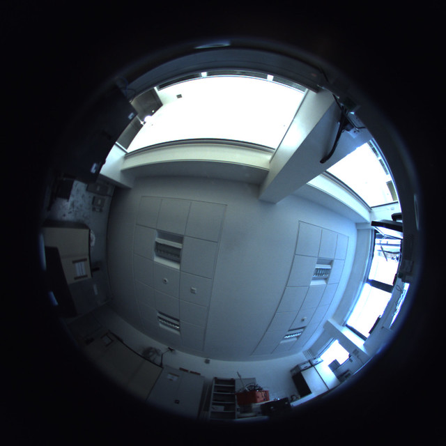
Sample ASI174MC image
Sample image from ASI174MC and Fukinon FE185C057HA-1 2/3" fisheye lens.
The complete control system is intended to timestamp and watermark images, change the recording cadence according to AuroraWatch UK status and solar elevation, record temperature and humidity, and control heating and fans.


The next giant leap for mankind is to the stars. While we are mostly earthbound — for now — that shouldn’t stop us from gazing upwards to marvel at the night sky. In saying that, if you’re an amateur astrophotographer looking to take long-exposure photos of the Milky Way and other stellar scenes, [Anthony Urbano] has devised a portable tracking setup to keep your photos on point.

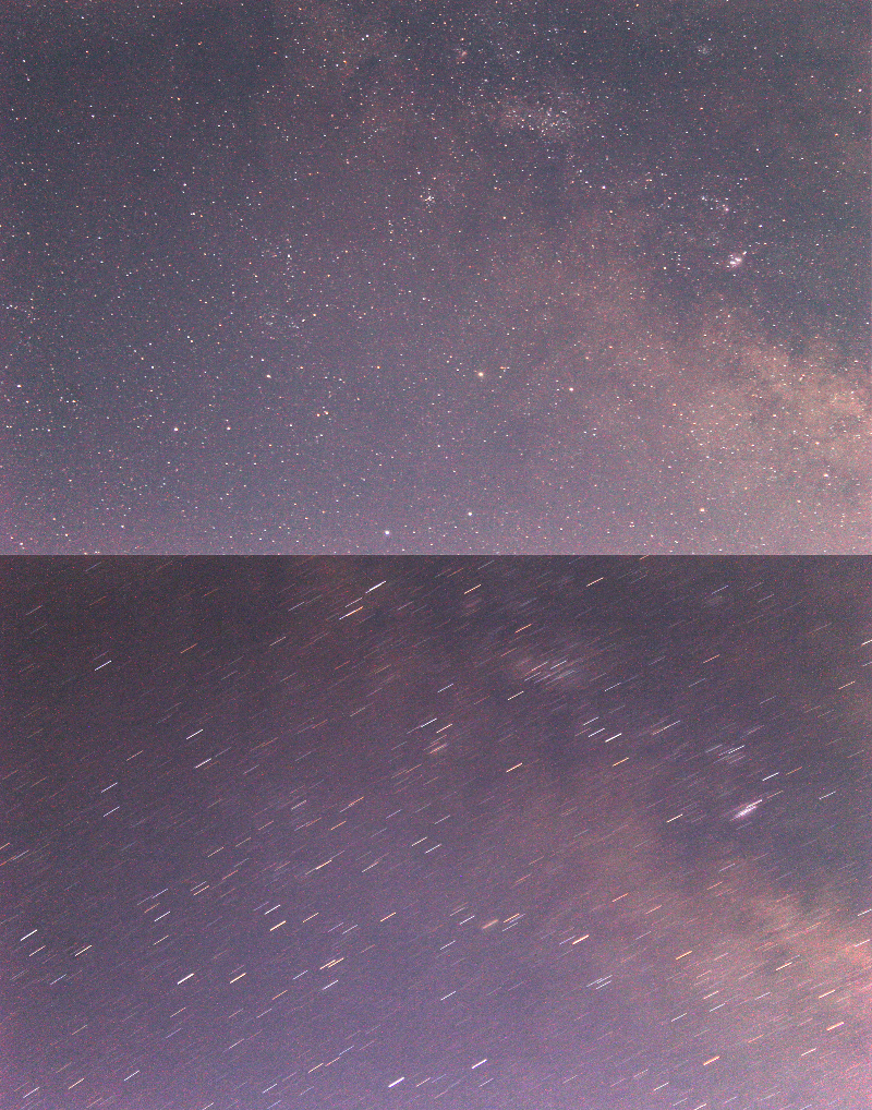
When taking pictures of the night sky, the earth’s rotation will cause light trails during long exposures. Designed for ultra-portability, [Urbano’s] rig uses an Arduino UNO controlled Sanryusha P43G geared stepper motor coupled to a camera mounting plate on a small tripod. The setup isn’t designed for anything larger than a DSLR, but is still capable of taking some stellar pictures.

55mm Exposure Comparison

A quartet of buttons and indicator LEDs allow [Urbano] to adjust the tracking speed and display the current speed; the key here is that it doesn’t require re-calibration for each use. The entire setup fits inside a standard camera bag, which makes for easier treks out into the wilds — away from light pollution — to truly capture the night sky.

[Urbano] has designed the project to be accessible to most amateur makers, but if you’re looking for a more involved setup, check out this star tracker — it uses 3D printed parts and has lasers!

[Thanks for sharing your project with us, Anthony Urbano!]


Filed under: Arduino Hacks, digital cameras hacks

It’s no secret that a lot of time, money, and effort goes into photographing and filming all that delicious food you see in advertisements. Mashed potatoes in place of ice cream, carefully arranged ingredients on subs, and perfectly golden french fries are all things you’ve seen so often that they’re taken for granted. But, those are static shots – the food is almost always just sitting on a plate. At most, you might see a chef turning a steak or searing a fillet in a commercial for a restaurant. What takes real skill – both artistic and technical – is assembling a hamburger in mid-air and getting it all in stunning 4k video.

That’s what [Steve Giralt] set out to do, and to accomplish it he had to get creative. Each component of the hamburger was suspended by rubber bands, and an Arduino timed and controlled servo system cut each rubber band just before that ingredient entered the frame. There’s even a 3D printed dual-catapult system to fling the condiments, causing them to collide in the perfect place to land in place on the burger.

In order to get this shot, [Steve] needed two things: precise timing and a robotic camera system to follow the burger down as it was assembled as it fell. The timing was taken care of with a control system he designed himself (which he’ll reuse for future projects). The robotic camera was a commercial unit capable of repeatedly following a preprogrammed path. You can see in the video below how it rotates around the hamburger to achieve a really cool 3D effect. Obviously a camera-wielding robot like the one [Steve] used is very expensive, but with a little ingenuity a DIY build is certainly possible.

[thanks to DMPalmer for the tip]


Filed under: Arduino Hacks, digital cameras hacks


  • Newsletter

    Sign up for the PlanetArduino Newsletter, which delivers the most popular articles via e-mail to your inbox every week. Just fill in the information below and submit.

  • Like Us on Facebook