Posts | Comments

Planet Arduino

Archive for the ‘camera’ Category

IMG_6106

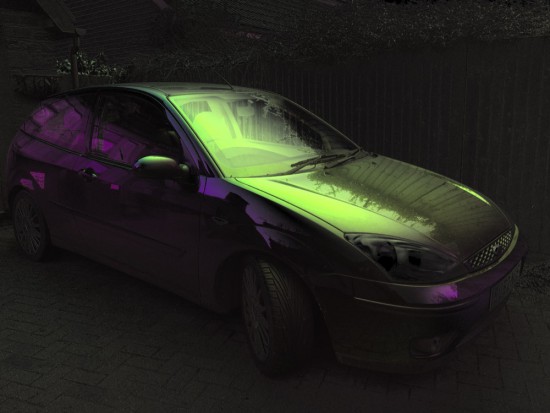
Taking great pictures means making them more vibrant enhancing saturation and contrast. Ynformatic has published some tips to help you do that by creating a DIY device to control a polarizer using an Arduino Pro Mini, an iPhone, and a screen from an auto-darkening welder’s mask.

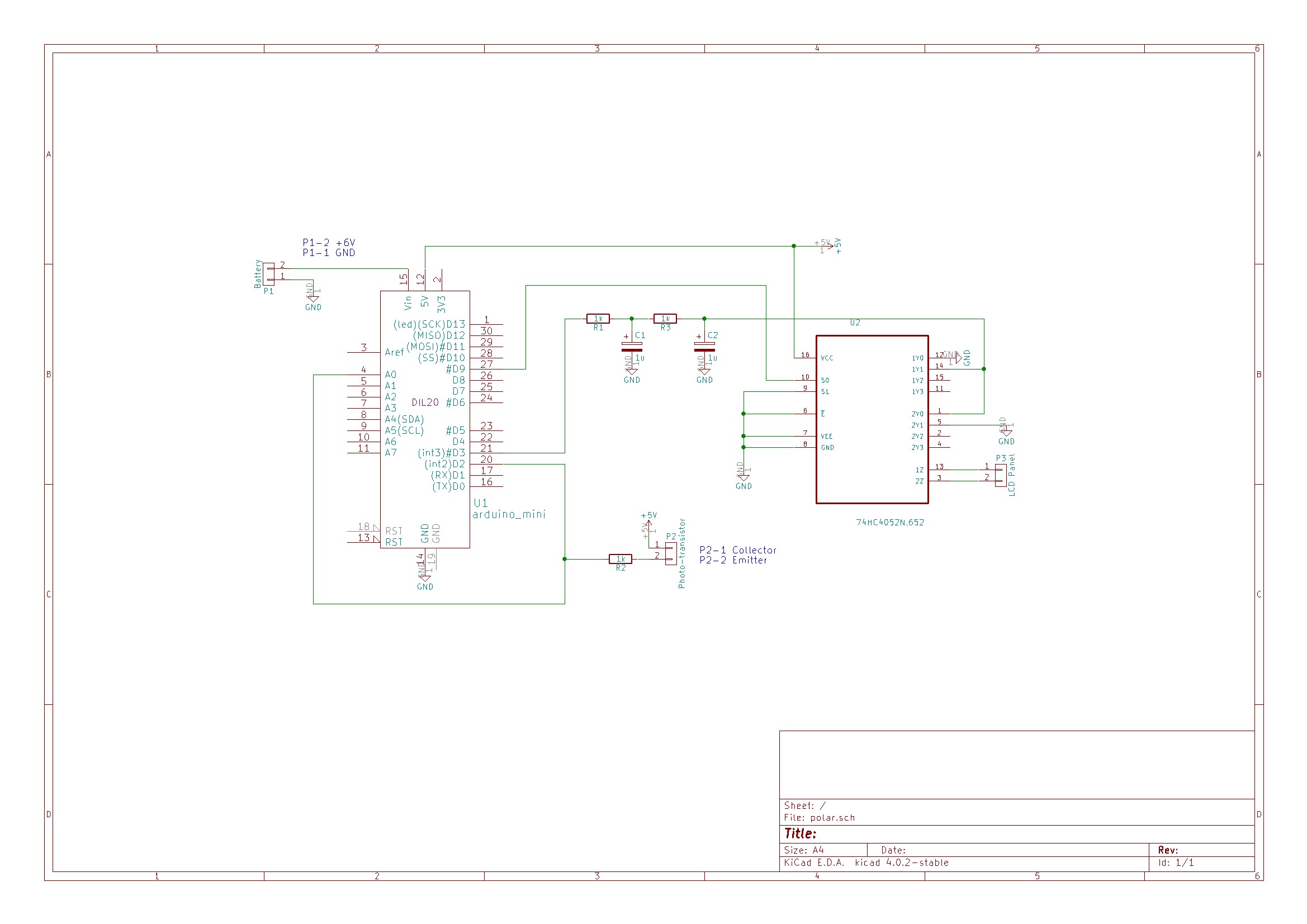
A phototransistor located facing the iPhone’s flashlight LED is connected to both an external interrupt pin and an analog pin. Short pulses on the LED cause interrupts in the Arduino code which are used to synchronize the polarizer. Long pulses on the LED cause the Arduino to enter calibration mode. The time interval between syncrhonization pulses is continuously measured and divided into three equal parts. On receiving a synchronization pulse the voltage is set to 0V for one part, to the 45 degree voltage for one part and finally to 5V for one part. Voltage for the polarizer is supplied from an Arduino PWM output pin. To get a reasonably stable output the PWM frequency was increased to 32 kHz and smoothed with a second order RC filter. The liquid crystal display will be damaged by a constant DC voltage so a CMOS switch is used to alternate the polarity. A 2 kHz square wave generated from a free running Arduino timer is used to drive the switching.

An iPhone app written in Swift is responsible for the user interface and image processing.

Explore the schematic in the picture below, while the full source code for the Arduino and iPhone can be downloaded from here.

schematic-1


Screen Shot 2015-12-04 at 1.45.57 PMThe purpose is clear. You don’t want your kids to steal your food from the cupboard, or from the fridge, or someone to open your locker. Or maybe you want to take pictures of your pet stealing food. Or maybe you are Dwight Schrute and you want to finally unmask […]

Read more on MAKE

The post You Can’t Touch This! Arduino Yún Alarm System appeared first on Make: DIY Projects, How-Tos, Electronics, Crafts and Ideas for Makers.

zombie02

Halloween time is a great moment to explore nice interactive projects and get inspired for installations for other selfie occasions. To spice up the office Donnie Plumly, a creative technologist, decided to make and share with us a molded zombie arm that takes pictures and post them to Twitter.

zombie03

He used a silicone arm (molded on his own hand ), a custom steel mount to clip to an office partition, and a vibration sensor hooked up to an Arduino Uno. Once the arm is slapped a photo will be taken using an IR Led and passed to the Eye-Fi card in the camera.

The photo is then saved into a Dropbox folder and, using If This Then That (IFTTT), posted to Twitter on the account @ZombieSelfie.

zombie

Donnie created also a very useful tutorial  on Instructable to make it yourself!

zombie04

We’d call it a robot, but [Eric Buijs] calls it a dolly. [Eric] bought a Makeblock starter robot kit last year, but never did anything with it. He recently wanted a camera dolly to help shoot project videos and the Makeblock hardware fit the bill.

[Eric] found that one of Makeblock’s example videos showed off a camera dolly but had no construction details. He cracked open the kit and got to work replicating what he had seen. Two 6V motors combined with a reduction gear, a belt, and some wheels, and the dolly now moves under computer control!

Speaking of the computer, the Makeblock kit came with an Arduino-compatible board called a Baseshield. [Eric] didn’t like the telephone-style connector used to interface the board with the outside world, so he junked the Baeshield and replaced it with an Arduino Leonardo. The only thing left was to make a camera mount, which [Eric] fabricated with plywood.

There’s still work to do. The dolly drifts a little to the left and the lack of suspension sometimes makes the video unusable. However, we are confident version two will be even better.

Judging by the number of past projects we’ve seen on dolly’s this is something a lot of people want to build. It is interesting to see just how many different ways people approach the same problem. If you haven’t seen Makeblock, there is a video about the starter kit [Eric] used below.


Filed under: Arduino Hacks, robots hacks

rImg_6372Make an automatic camera rig for shooting high-resolution panoramas with a point-and-shoot camera.

Read more on MAKE

The post Build an Automatic Photo Rig for Perfect Panoramas appeared first on Make: DIY Projects, How-Tos, Electronics, Crafts and Ideas for Makers.

Aug
04

New Project: Built a Motion Control Rig for Time-Lapse Photography

arduino, camera, camera rig, Electronics, Photography, photography rig, stepper motors, time-lapse, video Comments Off on New Project: Built a Motion Control Rig for Time-Lapse Photography 

sunriseIn this project, you'll learn how to use an Arduino microcontroller and a stepper motor to precisely control the panning of a camera during a time lapse.

Read more on MAKE

The post Built a Motion Control Rig for Time-Lapse Photography appeared first on Make: DIY Projects, How-Tos, Electronics, Crafts and Ideas for Makers.

What’s cooler than learning about timers and interrupts on AVRs? Well, if you’re like [Matt], you can use that learning experience to build something useful – in this case, a timer for various camera flashes.

There are two ways to measure the speed of a flash. The first is the lag between when a button is pressed and when the flash goes off. As long as this is consistent, everything’s okay. The second type of speed is the pulse width. When looking at a xenon flash as time vs. brightness, they have a large spike at the beginning followed by a significant amount of decay. LED flashes are pretty much one cycle of a square wave.

To measure both types of flash speed, [Matt] used a $0.50 photodiode an a 3.5mm mack that ties into the flash remote. These bits are wired up to an Arduino, a little bit of fun work with timers and interrupts happens, and [Matt] learns how fast his flash is.


Filed under: Arduino Hacks, digital cameras hacks
Jan
31

[Jordan] managed to cobble together his own version of a low resolution digital camera using just a few components. The image generated is pretty low resolution and is only in grey scale, but it’s pretty impressive what can be done with some basic hardware.

The heart of the camera is the image sensor. Most consumer digital cameras have tons of tiny receptors all jammed into the sensor. This allows for a larger resolution image, capturing more detail in a smaller space. Unfortunately this also usually means a higher price tag. [Jordan’s] sensor includes just a single pixel. The sensor is really just an infrared photodiode inside of a tube. The diode is connected to an analog input pin on an Arduino. The sensor can be pointed at an object, and the Arduino can sense the brightness of that one point.

In order to compile an actual image, [Jordan] needs to obtain readings of multiple points. Most cameras do this using the large array of pixels. Since [Jordan’s] camera only has a single pixel, he has to move it around and take each reading one at a time. To accomplish this, the Arduino is hooked up to two servo motors. This allows the sensor to be aimed horizontally and vertically. The Arduino slowly scans the sensor in a grid, taking readings along the way. A Processing application then takes each reading and compiles the final image.

Since this camera compiles an image so slowly, it sometimes has a problem with varying brightness. [Jordan] noticed this issue when clouds would pass over while he was taking an image. To fix this problem, he added an ambient light sensor. The Arduino can detect the amount of overall ambient light and then adjust each reading to compensate. He says it’s not perfect but the results are still an improvement. Maybe next time he can try it in color.


Filed under: Arduino Hacks
Jan
27

[AlxDroidDev] built himself a nice remote control box for CHDK-enabled cameras. If you haven’t heard of CHDK, it’s a pretty cool software modification for some Canon cameras. CHDK adds many new features to inexpensive cameras. In this case, [AlxDroidDev] is using a feature that allows the camera shutter to be activated via USB. CHDK can be run from the SD card, so no permanent modifications need to be made to the camera.

[AlxDroidDev’s] device runs off of an ATMega328p with Arduino. It operates from a 9V battery. The circuit contains an infrared receiver and also a Bluetooth module. This allows [AlxDroidDev] to control his camera using either method. The device interfaces to the camera using a standard USB connector and cable. It contains three LEDs, red, green, and blue. Each one indicates the status of a different function.

The Arduino uses Ken Shirrif’s IR Remote library to handle the infrared remote control functions. SoftwareSerial is used to connect to the Bluetooth module. The Arduino code has built-in functionality for both Canon and Nikon infrared remote controls. To control the camera via Bluetooth, [AlxDroidDev] built a custom Android application. The app can not only control the camera’s shutter, but it can also control the level of zoom.


Filed under: Arduino Hacks
Dec
20

OV7670 Camera Module DIY Guide

arduino, camera, image, JPEG, OV7670, photo Comments Off on OV7670 Camera Module DIY Guide 

camera-0706-A

This camera module can perform image processing such as AWB (auto white balance), AE (automatic exposure) and AGC (automatic gain control), for the video signal coming from CMOS sensor. What’s more, in fusion of other advanced technology such as image enhancement processing under low illumination, and image noise intelligent forecast and suppress, this module would output high quality digital video signals by standard CCIR656 interface. OV7670 built-in JPEG decoder supported reatime encoding for collected image, and external controller can easily read the M – JPEG video streams, achieving the camera design of double stream. OV7670 supported motion detection and OSD display function of screen characters and pattern overlay, capable of self-defining detection area and sensitivity.

OV7670 Camera Module DIY Guide - [Link]


  • Newsletter

    Sign up for the PlanetArduino Newsletter, which delivers the most popular articles via e-mail to your inbox every week. Just fill in the information below and submit.

  • Like Us on Facebook