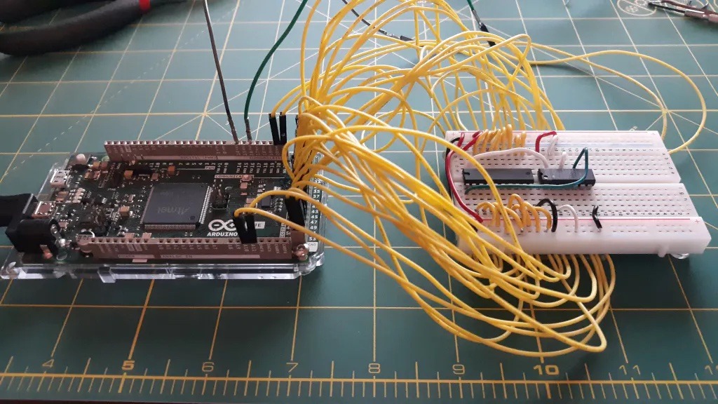
Breadboards are the first tool you break out in any prototyping journey and almost every project will utilize a breadboard at some point. Those breadboards often turn into a rats’ nest of overlapping wires that are difficult to trace, which makes it difficult to create an accurate schematic when it is time to design your PCB. To make your life easier, Nick Bild came up with a script that analyzes your physical breadboard to automatically generate a KiCAD schematic.
A breadboard is, at its core, a series of connectors. This script’s purpose is to identify every connection and associate it with the corresponding pin on a component. It is able to do that using a special breadboard that has every row of pins connected to an Arduino Due board I/O pin. A Python script running on a connected PC then checks every row for continuity. The user then inputs the component located at connection, and the script will draw a KiCAD schematic with wires between every component’s pins.
This script does have some serious limitations. The most obvious is that many ICs either don’t have internal continuity for every pin or only have internal continuity in certain states. To overcome that, the user must insert jumpers in place of some components. The user must also enter the component associated with each connection, because the script has no way of identifying components — it only checks for continuity. But even with those limitations, Schematic-o-matic can save you a lot of time and effort when you create schematics for particularly complex breadboard circuits.
The truth is, we never entirely got to grips with Arduino documentation. Until now. Now there’s a new standard for gathering together product info, tech specs and tutorials, that we’re calling Arduino Docs. We’re excited to share it with the Arduino community who’ll soon be able to help it grow.
It began with the Uno
When the Arduino Uno was launched around 15 years ago, its detailed documentation was a vital part of its success. It wouldn’t be at all unreasonable to say that its online resources were a driving factor in the establishment and growth of the primordial Arduino community.
But you’re probably quite aware of Arduino’s history, and the rapid growth that followed. Creating, organizing and maintaining that level of documentation around each and every board became a huge task. The complexity was one thing, but the open-source nature also meant that a lot of third party content was generated. Which is great, and is still very much encouraged, but it also muddied the waters of supporting content.
So getting all that essential info together in one place, while providing a great experience for the users, has been a passion project for a lot of people at Arduino. And now, it’s ready.
Which brings us back to today, and the launch of a whole new approach to the online presence of Arduino boards. Welcome to Arduino Docs.
The All New Arduino Docs Site
The new Arduino Docs site launches with a detailed, but easy-to-use breakdown of everything you ever wanted to know about the official boards and products.
Every product will get its own page, broken down into standardized sections so you have instant, easy access to what you need.
Overview: You’ll begin here when you take a look at a board on the Arduino Docs site. It’s a bird’s-eye-view of the board’s description and purpose, its main features, tech specs, revision logs (where applicable) and compatibility options.
Essentials: This section gets you started with using the board in question. Here you’ll find quick start guides, suggestions for libraries, and useful basics on using Arduino. Perfect for newcomers or anyone needing a refresher.
Tutorials: Any and all tutorials connected to the board will be marshalled here. You’ll never have to go hunting when you’re looking to build something awesome. These tutorials will showcase the different features of each board, giving you a full understanding of what’s possible.
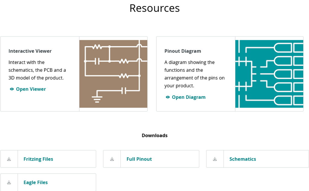
Resources: This is where we’ll keep the datasheets, downloads, pinout diagrams, schematics and other useful documents and files.
It’s been no small feat collating all this information, and reformatting into something that’s as useful for beginners as it is for experts and engineers. It’ll kick off with over 130 tutorials, dozens of boards, and a great selection of shields, all given a brand new home.
But it’s not just about the hardware. The new Arduino Docs site aims to be the most encyclopedic resource we’ve ever compiled, so it includes sections for software (such as the IDEs), Cloud (for the web editor and other Arduino Cloud tools) and a great asset for understanding the foundations of Arduino’s approach to electronics.
Cool Community Content
Lots of companies say they’re all about community. But in our case it’s actually true! Arduino isn’t a company or a board or a platform. It’s a community.
You guys created much of the content, tutorials and documentation out there. That’s not going to change now that we’ve launched Arduino Docs. GitHub is home to the whole system (we’re tech nerds, we can’t help it). That means members of the community will soon be able to add, edit and influence the Arduino Docs content.
The content team will review and approve submissions and branches made through GitHub. So what you’re seeing right now is the embryonic stage of Arduino Docs. We envisage amazing things once the community is able to get involved. Sign up to our newsletter so we can keep you posted on when that becomes possible, and about updates, leaks and more.
We’re very proud of the work that the various internal teams have done in making this happen. We hope you are too, and as always we really want any and all feedback you have on this new and valuable Arduino resource.
Please go and take a look, and do stop by the forums to tell us all about your experience.
Patrick Griffin is a maintenance technician working in the plastics industry for the last 20+ years with primary focus being the repair, upkeep, & design of electrical, electronic, automation, and both relay & PLC control logic. He submitted his project to Arduino blog about using Teensy Arduino on a Maac vacuum former:
This story revolves around one of the workhorse machines in the company where I work: a Maac vacuum former. It is a solid, well-designed machine with a solid, well-designed control system that Maac contracted out to the Electro Cam systems group. As with any industrial equipment, as time goes by the OEM develops new products that replace their old stuff, technologies advance, and eventually they start the formal process of obsoleting their older inventory.
The situation started out years ago, long before I arrived on the scene, when the company I work for hired a contractor to add some automation to the Maac. When the automation was added almost all of the Electro Cam system was necessarily replaced with an Allen-Bradley SLC500 PLC to provide the changes in logic & the additional I/O points to do all of the new functions. The only Electro Cam components left in the Maac are the parts in the 84 zone oven controller.
We have been aware that more and more of it’s components, especially the Electro Cam controls, were being obsoleted. Recently we were put in the position to ask ourselves what our options are when one of these proprietary controls have a permanent catastrophic failure. What we learned was that we would be given few options through the official channels. We would have to leave the machine down and idle for an undetermined amount of time while the failed component was sent to Electro Cam for assessment and possible repair. This would certainly take longer than a week, but my gut says it would be closer to a month. There are also no guarantees that the part could be repaired at all. We were quoted a price for a replacement as starting at $4500, but with no promises.
Not having a replacement for a proprietary single-sourced part on the shelf is scary. Worse is when that single source says that they really can’t help you. This is one of several (maybe many) triggers for the maintenance department that I am a part of to fly wildly into a re-engineering frenzy.
Read the complete story and take a look at the schematics, on his website.
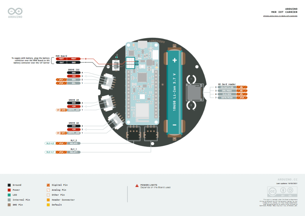
Pighixxx, from the Arduino forum, has created several pinout diagrams for the Arduino UNO and for several ATMega microcontrollers, such as the ATMega 328 and the ATMega 1284p.
These diagrams provide a clear picture about how to use each pin of the board and can be used as real “cheatsheets” for your own DIY projects. You can download them from here. Enjoy!
About
Planet Arduino is, or at the moment is wishing to become, an aggregation of public weblogs from around the world written by people who develop, play, think on Arduino platform and his son. The opinions expressed in those weblogs and hence this aggregation are those of the original authors. Entries on this page are owned by their authors. We do not edit, endorse or vouch for the contents of individual posts. For more information about Arduino please visit www.arduino.cc
You are currently browsing the archives for the Schematics category.