Posts | Comments

Planet Arduino

Archive for the ‘mbed’ Category

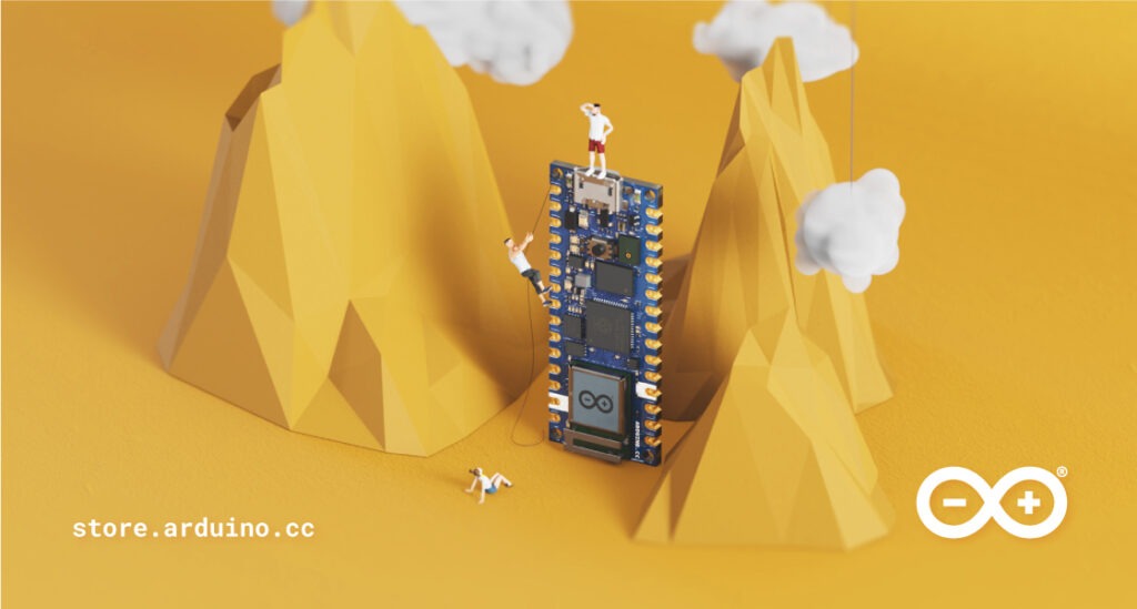
It was back in January that we first introduced you to the Arduino Nano RP2040 Connect. The first Arduino board to include Raspberry Pi silicon. It’s been a roller coaster ride getting it to you, and enthusiasm during the wait has been incredibly encouraging. The wait, you’ll be glad to hear, is over.

The Arduino Nano RP2040 Connect mountain climbing

The RP2040 Processor

Working with the Raspberry Pi Foundation is nothing short of a pleasure. The teams there make some incredible devices, and their first in-house silicon is no exception. These guys get it.

This system-on-a-chip is a 32-bit dual-core ARM Cortex-M0+ microcontroller, clocked at 133MHz and is powerful enough to run TensorFlow Lite. It’s young, but proving to be incredibly popular with makers, as well as electronics manufacturers. It’s going to be incredibly exciting to see how the Arduino community reacts to it. We can only imagine what you guys can achieve with the extra features of the Nano RP2040 Connect board.

Welcome the Arduino Nano RP2040 Connect

So it was an easy choice for Arduino to put an RP2040 at the core of a new board. We felt so strongly about the excellence of this new chip that we knew it deserved a powerful, premium Nano board that is unrivalled in terms of features.

First and foremost is the inclusion of the u-blox NINA-W102 WiFi and Bluetooth radio module. Nano users are probably quite familiar with this excellent module already.

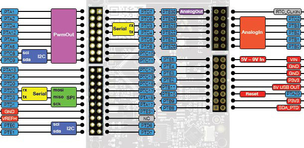
Coupled with a six-axis machine learning-capable IMU motion sensor, on-board microphone for sound and voice activation, an RGB LED and loads of multi-function GPIO pins, this is the project maker’s dream come true. And all on such a tiny board.

Nano RP2040 Connect in the Cloud

Just like everything Arduino, the hardware of the Nano RP2040 Connect is only half the story.

Right off the bat this device is fully compatible with the Arduino Cloud. It landed at just the right moment, as Arduino Cloud plans were given an overhaul. These offer a lot more on the free tier, while bringing in a new Entry Plan that really unlocks the power of the cloud.

Nano RP2040 Connect to Arduino Cloud

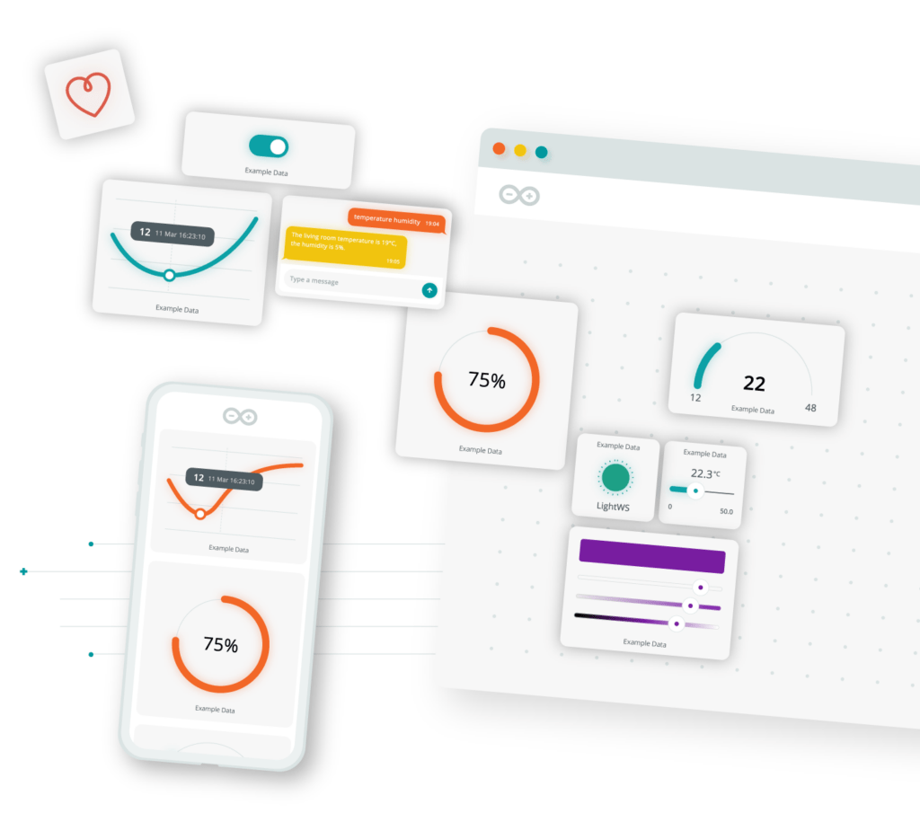
Because the Nano RP2040 Connect is a connected device, this opens up all kinds of possibilities. Not least of all over-the-air updates and programming. This alone can make a Cloud accompaniment to the board worthwhile. It gives you full, incredibly easy access to the hardware. This is true even after it’s been deployed, installed or buried in the guts of a project. If it’s got a WiFi signal, you can do everything as if it was plugged in by USB. Furthermore, it has the added bonus of smartphone control through the Arduino IoT Remote app.

The Cloud even makes it super easy for your Nano RP2040 Connect to communicate wirelessly with other boards. Any devices connected to your Arduino Cloud can communicate, and we’re not just talking about official Arduino boards.

So Much Software

A couple of weeks ago we updated the official Arduino Mbed Core to provide native RP2040 support.

The plug-and-play nature of the Arduino Core means you can use existing sketches you made for, say, a Nano 33 BLE Sense on your brand new Nano RP2040 Connect. So you can have this little workhorse up and running within minutes, if you’ve already been working on some project sketches. Plus, it’s compatible with the entire RP2040 software ecosystem, so if this is an upgrade for an existing RP2040 board, you’re good to go.

If you’re just getting started on sketches for the device, it offers full support for MicroPython. There’s even a free OpenMV license bundled in, for any machine vision projects you might have planned.

Arduino Nano RP2040 Connect

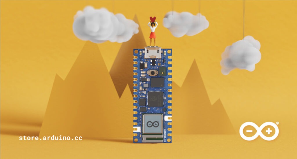
Go Get Your Arduino Nano RP2040 Connect

Yes, there’s a limited supply at launch. We built as many as possible for the first run. But a lot have been sent out to our reseller partners. So head on over to the store right now if you want to be one of the first to get this premium RP2040 board.

If you want to stay up to date on all things Arduino Nano RP2040 Connect, make sure you’re signed up to our email list. From there we’ll keep you advised on restocking, new updates, special offers and everything else to do with this tiny, but mighty, board.

The post The Arduino Nano RP2040 Connect is here appeared first on Arduino Blog.

Arduino support for the Raspberry Pi RP2040 chip is available now using the official Arduino Mbed Core. This is obviously very important, and exciting, for the upcoming Arduino Nano RP2040 Connect. But it goes beyond the Arduino device to also bring support to other boards built around the RP2040 chip.

Arduino Core and Mbed OS

Arduino is no stranger to Mbed OS. It’s a hugely important platform and operating system in the IoT space. This is due toits support for Cortex-M microcontrollers and its real-time operating system capabilities. So a lot of work was done when Mbed OS was adopted for the Nano 33 BLE and Nano 33 BLE Sense devices. Since all Mbed infrastructure and drivers were in place, we could easily support all new Arduino boards with minimal effort. Including new ones like the Portenta H7 and Nano RP2040 Connect.

Arduino Mbed Core for RP2040

This makes the Arduino Core plug-and-play, and an easy choice for getting your devices up and running quickly. We provide two cores; one for our Nano RP2040 Connect board, and one for other RP2040-based boards, including the Raspberry Pi Pico. As the core is based on Mbed OS you can choose between using the Arduino’s API or Mbed’s.

If you’d like to support any other RP2040 board with its custom features you can do so. It requires very little effort by cloning and tweaking the Arduino Mbed Core.

Ready for the Nano RP2040 Connect

All Arduino APIs are standardized, which means they can be used on all boards. If you have a sketch for your Nano 33 BLE, you can now upload it to a Nano RP2040 Connect and run it without making any changes.

In effect this means you can create sketches for the new Arduino board, even if you don’t have your hands on it yet. It also makes project upgrades very easy. Nor does the Arduino Core require a custom bootloader for RP2040 devices, as it uses the ROM-based bootloader from Raspberry Pi.

Check out the Arduino Core Mbed right here. And sign up to our Nano RP2040 Connect contact list for more news as it happens.

The post Arduino Mbed Core for RP2040 Boards appeared first on Arduino Blog.

Sometimes it seems like Arduino is everywhere. However, with a new glut of IoT processors, it must be quite a task to keep the Arduino core on all of them. Writing on the Arduino blog, [Martino Facchin], Arduino’s chief of firmware development, talks about the problem they faced supporting two new boards from Nordic.

The boards, the Nano 33 BLE and Nano 33 BLE Sense are based on an ARM Cortex M4 CPU from Nordic. The obvious answer, of course, is to port the Arduino core over from scratch. However, the team didn’t want to spend the time for just a couple of boards. They considered using the Nordic libraries to interact with the hardware, but since that is closed source, it didn’t really fit with Arduino’s sensitivities. However, in the end, they took a third approach which could be a very interesting development: they ported the Arduino core to the Mbed OS. There’s even an example of loading a sketch on top of Mbed available from [Jan Jongboom].

On the one hand, this has two big advantages: in theory, Arduino can now run on anything that supports Mbed, which is quite a lot. Second, even though the system retains the simplicity of Arduino, the entire Mbed system is available to Arduino developers and vice versa.

On the other hand, you could argue that if you have Mbed, you don’t really need Arduino. While much is made about Arduino’s simplicity, it is really a C++ program with two predefined functions and an IDE that builds your code without as much explicit help as you’d expect. However, the wide variety of code that supports Arduino should be of interest since you could just use it from either an Arduino or Mbed program without much effort.

This might make some of our favorite Mbed labs projects more popular. If you want to see our take on an Mbed project, you can turn it into a signal generator.

Thanks [halherta] for the tip.

Oct
18

Review – NXP LPC800-MAX Development Board

LPC800, LPC800-MAX, LPC810, LPCxpresso, mbed, review, tronixstuff Comments Off on Review – NXP LPC800-MAX Development Board 

Introduction

Now and again we examine various development boards designed for use with the mbed development platform for ARM microcontrollers, such as the the original mbed unit and the Freescale Freedom FRDM-KL25Z – and now we have another one from NXP … their new LPC800-MAX development board:

LPC800-MAX front PCB

LPC800-MAX rear PCB

Although the LPC800-MAX works with the mbed online compiler, you’re not limited to that. NXP have also supplied free offline development tools based on the Eclipse IDE.

Hardware specification

The board is based on the NXP LPC812 with an ARM Cortex-M0+ Core running at 30 MHz. The LPC812 has 16KB flash memory, and 4KB RAM. For I/O you have 3 x USARTs, 2 x SPI ports,  one comparator, and one I2C port. The serial lines are brought out to a separate serial expansion connector to allow easy connection to a range of expansion boards from the manufacturer. An RGB LED is fitted to the board for all the “hello, world” fun you could want, and for extra I/O (and I2C practice) there’s a four-channel NXP PCF8591 ADC (and also gives you one DAC as well – convenient) along with a PCA9672 I/O expander IC for more GPIO. 

If you’re using the offline development IDE you can also make use of the NXP hardware debugging interface as well. Users of the physically-narrow range of NXP LPC development boards will also recognise the two parallel rows of pinouts down the length of the PCB, and Arduino users will recognise the header sockets (more on those later). When you receive the board – you just receive the board, so you’ll need a typical microUSB cable. Finally, you can download the LPC800 MAX schematic for further examination.

What is mbed anyway?

mbed is a completely online development environment. That is, in a manner very similar to cloud computing services such as Google Docs. However there are some pros and cons of this method. The pros include not having to install any software on the PC – as long as you have a web browser and a USB port you should be fine; any new libraries or IDE updates are handled on the server leaving you to not worry about staying up to date; and the online environment can monitor and update your MCU firmware if necessary.

However the cons are that you cannot work with your code off-line (no working in-flight) and there may be some possible privacy issues. Here’s an example of the environment:

mbed compiler screen

As you can see the IDE is quite straight-forward. All your projects can be found on the left column, the editor in the main window and compiler and other messages in the bottom window. There’s also an online support forum, an official mbed library and user-submitted library database, help files and so on – so there’s plenty of support.

Code is written in C/C++ style and doesn’t present any major hurdles. When it comes time to run the code, the online compiler creates a downloadable binary file which is copied over to the hardware via USB, from which point you reset the board and off it goes.

If you’re using the LPC800-MAX with mbed, be sure to follow the “Getting Started” guide and also check for the latest firmware from the mbed handbook. And although the mbed board appears as a USB storage device, you can still have serial communication with a PC using a virtual serial port via the USB cable connected between the PC and the LPC800-MAX.

Arduino form-factor compatibility

You will notice the header sockets physically match the Arduino Uno R3 specification, so you can drop in an Arduino shield. However the board runs on 3.3V and is 5V-tolerant, so it’s preferable your shields or new designs are good for 3.3V operation. Furthermore, as the onboard LPC812 doesn’t have as much analogue and digital I/O as an ATmega328P found on the Arduino Uno, the extra I/O are provided by two external ICs via I2C. Four analogue inputs are provided by the onboard NXP PCF8591 ADC (and also gives you one DAC as well – convenient) – and the equivalent A4 and A5 pins are not ADC, instead they’re just I2C SDA and SCL respectively.

The extra digital I/O pins are provided via I2C by the aforementioned PCA9672 I/O expander IC. Upon reflection you’d have to be very keen to use a specific Arduino shield as some extra coding would be required to deal with the required I/O – however on the other hand you can easily add external circuitry with blank Arduino protoshields for new projects. Finally, here’s a pin map of the shield connectors.

LPC-800 pin map

Not a fan of mbed? Offline tools

NXP have also made their LPCXpressoIDE based on Eclipse available for free download for all platforms - http://lpcware.com/lpcxpresso/download. The free version is good for up to 256 KB code size (provided you register the software) which more than covers the requirements for this and other LPC800 products:

LPCXpresso IDE screenshot

For more information and support, there is a huge repository of information on the NXP website.

Where to get an LPC800-MAX

The board is manufactured and sold by Embedded Artists. At the time of writing the board retails for €15, which is around US$21. NXP also have a range of LPC800 microcontrollers, including very inexpensive through-hole 8-pin versions which are available from the usual retailers. And adafruit of all places have a US$13 starter pack based around the DIP LPC810, which is an interesting 32-bit alternative to the ATtinys out there.

Conclusion

If you’re interested in working with the NXP LPC800-series of microcontrollers, the LPC800-MAX board is a very convenient development board considering the included debugger, Arduino protoshield capability, external GPIO expander and ADC/DAC and onboard LED – as well as the free IDE.

If you enjoy the mbed development environment, the board gives you another hardware option. However if you’re an Arduino user looking for a cheap way of getting a faster board whilst using your existing environment – this is not for you. The product under review was purchased without the knowledge of the supplier.

Full-sized images can be found on flickr. And while you’re here – are you interested in Arduino? Check out my new book “Arduino Workshop” from No Starch Press.

In the meanwhile have fun and keep checking into tronixstuff.com. Why not follow things on twitterGoogle+, subscribe  for email updates or RSS using the links on the right-hand column? And join our friendly Google Group – dedicated to the projects and related items on this website. Sign up – it’s free, helpful to each other –  and we can all learn something.

The post Review – NXP LPC800-MAX Development Board appeared first on tronixstuff.

In this article we examine the mbed rapid prototyping platform with the Freescale FRDM-KL25Z ARM® Cortex™-M0+ development board.

Introduction

A while ago we looked at the mbed rapid prototyping environment for microcontrollers with the cloud-based IDE and the NXP LPC1768 development board, and to be honest we left it at that as I wasn’t a fan of cloud-based IDEs. Nevertheless, over the last two or so years the mbed platform has grown and developed well – however without too much news on the hardware side of things. Which was a pity as the matching development boards usually retailed for around $50 … and most likely half the reason why mbed didn’t become as popular as other rapid development platforms.

Also – a few months ago – we received the new Freescale Freedom FRDM-KL25Z development board from element14. I started to write about using the board but frankly it did my head in, as at the time the IDE was almost a one gigabyte download and the learning curve too steep for the time I had available. Which was a pity as the board is inexpensive and quite powerful. So the board went into the “miscellaneous dev kit” box graveyard. Until now. Why?

You can now use the Freedom board with mbed. 

It isn’t perfect – yet – but it’s a move in the right direction for both mbed and Freescale. It allows educators and interested persons access to a very user-friendly IDE and dirt-cheap development boards.

What is mbed anyway?

mbed is a completely online development environment. That is, in a manner very similar to cloud computing services such as Google Docs or Zoho Office. However there are some pros and cons of this method. The pros include not having to install any software on the PC – as long as you have a web browser and a USB port you should be fine; any new libraries or IDE updates are handled on the server leaving you to not worry about staying up to date; and the online environment can monitor and update your MCU firmware if necessary. However the cons are that you cannot work with your code off-line, and there may be some possible privacy issues. Here’s an example of the environment (click to enlarge):

As you can see the IDE is quite straight-forward. All your projects can be found on the left column, the editor in the main window and compiler and other messages in the bottom window. There’s also an online support forum, an official mbed library and user-submitted library database, help files and so on – so there’s plenty of support. Code is written in C/C++ style and doesn’t present any major hurdles. When it comes time to run the code, the online compiler creates a downloadable binary file which is copied over to the hardware via USB.

And what’s a Freedom board?

It’s a very inexpensive development board based on the Freescale ARM® Cortex™-M0+ MKL25Z128VLK4 microcontroller. How inexpensive? In Australia it’s $9 plus GST and delivery.

Features include  (from the product website):

  • MKL25Z128VLK4 MCU – 48 MHz, 128 KB flash, 16 KB SRAM, USB OTG (FS), 80LQFP
  • Capacitive touch “slider,” MMA8451Q accelerometer, tri-color LED
  • Easy access to MCU I/O
  • Sophisticated OpenSDA debug interface
  • Mass storage device flash programming interface (default) – no tool installation required to evaluate demo apps
  • P&E Multilink interface provides run-control debugging and compatibility with IDE tools
  • Open-source data logging application provides an example for customer, partner and enthusiast development on the OpenSDA circuit

And here it is:

In a lot of literature about the board it’s mentioned as being “Arduino compatible”. This is due to the layout of the GPIO pins – so if you have a 3.3 V-compatible Arduino shield you may be able to use it – but note that the I/O pins can only sink or source 3 mA (from what I can tell) – so be careful with the GPIO . However on a positive side the board has the accelerometer and an RGB LED which are handy for various uses. Note that the board ships without any stacking header sockets, but element14 have a starter pack with those and a USB cable for $16.38++.

Getting started

Now we”ll run through the process of getting a Freedom board working with mbed and creating a first program. You’ll need a computer (any OS) with USB, an Internet connection and a web browser, a USB cable (mini-A to A) and a Freedom board. The procedure is simple:

  1. Download and install the USB drivers for Windows or Linux from here.
  2. Visit mbed.org and create a user account. Check your email for the confirmation link and follow the instructions within.
  3. Plug in your Freedom board – using the USB socket labelled “OpenSDA”. It will appear as a disk called “bootloader”
  4. Download this file and copy it onto the “bootloader” drive
  5. Unplug the Freedom board, wait a moment – then plug it back in. It should now appear as a disk called “MBED”, for example (click to enlarge):

There will be a file called ‘mbed’ on the mbed drive – double-click this to open it in a web browser. This process activates the board on your mbed account – as shown below (click to enlarge):

Now you’re ready to write your code and upload it to the Freedom board. Click “Compiler” at the top-right to enter the IDE.

Creating and uploading code

Now to create a simple program to check all is well. When you entered the IDE in the previous step, it should have presented you with the “Guide to mbed Online Compiler”. Have a read, then click “New” at the top left. Give your program a name and click OK. You will then be presented with a basic “hello world” program that blinks the blue LED in the RGB module. Adjust the delays to your liking then click “Compile” in the toolbar.

If all is well, your web browser will present you with a .bin file that has been downloaded to the default download directory. (If not, see the error messages in the area below the editor pane). Now copy this .bin file to the mbed drive, then press the reset button (between the USB sockets) on the Freedom board. Your blue LED should now be blinking.

Moving forward

You can find some code examples that demonstrate the use of the accelerometer, RGB LED and touch sensor here. Here’s a quick video of the touch sensor in action:

So which pin is what on the Freedom board with respect to the mbed IDE? Review the following map:

All the pins in blue – such as PTxx can be referred to in your code. For example, to pulse PTA13 on and off every second, use:

#include "mbed.h"
DigitalOut pulsepin(PTA13);
int main() {
 while(1) {
 pulsepin = 1;
 wait(1);
 pulsepin = 0;
 wait(1);
 }
}

The pin reference is inserted in the DigitalOut assignment and thus “pulsepin” refers to PTA13. If you don’t have the map handy, just turn the board over for a quick-reference (click to enlarge):

Just add “PT” to the pin number. Note that the LEDs are connected to existing GPIO pins: green – PTB19, red – PTB18 and blue – PTB.

Where to from here? 

It’s up to you. Review the Freedom board manual (from here) and the documentation on the mbed website, create new things and possibly share them with others via the mbed environment. For more technical details review the MCU data sheet.

Conclusion

The Freedom board offers a very low cost way to get into microcontrollers and programming. You don’t have to worry about IDE or firmware revisions, installing software on locked-down computers, or losing files. You could teach a classroom full of children embedded programming for around $20 a head (a board and some basic components). Hopefully this short tutorial was of interest. We haven’t explored every minute detail – but you now have the basic understanding to move forward with your own explorations.

The Freescale Freedom FRDM-KL25Z development board used in this article was a promotional consideration supplied by element14.

Have fun and keep checking into tronixstuff.com. Why not follow things on twitterGoogle+, subscribe  for email updates or RSS using the links on the right-hand column, or join our Google Group – dedicated to the projects and related items on this website. Sign up – it’s free, helpful to each other –  and we can all learn something.

In this article we examine the mbed rapid prototyping platform with the Freescale FRDM-KL25Z ARM® Cortex™-M0+ development board.

Introduction

A while ago we looked at the mbed rapid prototyping environment for microcontrollers with the cloud-based IDE and the NXP LPC1768 development board, and to be honest we left it at that as I wasn’t a fan of cloud-based IDEs. Nevertheless, over the last two or so years the mbed platform has grown and developed well – however without too much news on the hardware side of things. Which was a pity as the matching development boards usually retailed for around $50 … and most likely half the reason why mbed didn’t become as popular as other rapid development platforms.

Also – a few months ago – we received the new Freescale Freedom FRDM-KL25Z development board from element14. I started to write about using the board but frankly it did my head in, as at the time the IDE was almost a one gigabyte download and the learning curve too steep for the time I had available. Which was a pity as the board is inexpensive and quite powerful. So the board went into the “miscellaneous dev kit” box graveyard. Until now. Why?

You can now use the Freedom board with mbed. 

It isn’t perfect – yet – but it’s a move in the right direction for both mbed and Freescale. It allows educators and interested persons access to a very user-friendly IDE and dirt-cheap development boards.

What is mbed anyway?

mbed is a completely online development environment. That is, in a manner very similar to cloud computing services such as Google Docs or Zoho Office. However there are some pros and cons of this method. The pros include not having to install any software on the PC – as long as you have a web browser and a USB port you should be fine; any new libraries or IDE updates are handled on the server leaving you to not worry about staying up to date; and the online environment can monitor and update your MCU firmware if necessary. However the cons are that you cannot work with your code off-line, and there may be some possible privacy issues. Here’s an example of the environment:

mbedcompiler

As you can see the IDE is quite straight-forward. All your projects can be found on the left column, the editor in the main window and compiler and other messages in the bottom window. There’s also an online support forum, an official mbed library and user-submitted library database, help files and so on – so there’s plenty of support. Code is written in C/C++ style and doesn’t present any major hurdles. When it comes time to run the code, the online compiler creates a downloadable binary file which is copied over to the hardware via USB.

And what’s a Freedom board?

It’s a very inexpensive development board based on the Freescale ARM® Cortex™-M0+ MKL25Z128VLK4 microcontroller. How inexpensive? In Australia it’s $9 plus GST and delivery.

Features include  (from the product website):

  • MKL25Z128VLK4 MCU – 48 MHz, 128 KB flash, 16 KB SRAM, USB OTG (FS), 80LQFP
  • Capacitive touch “slider,” MMA8451Q accelerometer, tri-color LED
  • Easy access to MCU I/O
  • Sophisticated OpenSDA debug interface
  • Mass storage device flash programming interface (default) – no tool installation required to evaluate demo apps
  • P&E Multilink interface provides run-control debugging and compatibility with IDE tools
  • Open-source data logging application provides an example for customer, partner and enthusiast development on the OpenSDA circuit

And here it is:

topside

In a lot of literature about the board it’s mentioned as being “Arduino compatible”. This is due to the layout of the GPIO pins – so if you have a 3.3 V-compatible Arduino shield you may be able to use it – but note that the I/O pins can only sink or source 3 mA (from what I can tell) – so be careful with the GPIO . However on a positive side the board has the accelerometer and an RGB LED which are handy for various uses. Note that the board ships without any stacking header sockets, but element14 have a starter pack with those and a USB cable for $16.38++.

Getting started

Now we”ll run through the process of getting a Freedom board working with mbed and creating a first program. You’ll need a computer (any OS) with USB, an Internet connection and a web browser, a USB cable (mini-A to A) and a Freedom board. The procedure is simple:

  1. Download and install the USB drivers for Windows or Linux from here.
  2. Visit mbed.org and create a user account. Check your email for the confirmation link and follow the instructions within.
  3. Plug in your Freedom board – using the USB socket labelled “OpenSDA”. It will appear as a disk called “bootloader”
  4. Download this file and copy it onto the “bootloader” drive
  5. Unplug the Freedom board, wait a moment – then plug it back in. It should now appear as a disk called “MBED”, for example :

mbeddrive

There will be a file called ‘mbed’ on the mbed drive – double-click this to open it in a web browser. This process activates the board on your mbed account – as shown below:

registered

Now you’re ready to write your code and upload it to the Freedom board. Click “Compiler” at the top-right to enter the IDE.

Creating and uploading code

Now to create a simple program to check all is well. When you entered the IDE in the previous step, it should have presented you with the “Guide to mbed Online Compiler”. Have a read, then click “New” at the top left. Give your program a name and click OK. You will then be presented with a basic “hello world” program that blinks the blue LED in the RGB module. Adjust the delays to your liking then click “Compile” in the toolbar.

If all is well, your web browser will present you with a .bin file that has been downloaded to the default download directory. (If not, see the error messages in the area below the editor pane). Now copy this .bin file to the mbed drive, then press the reset button (between the USB sockets) on the Freedom board. Your blue LED should now be blinking.

Moving forward

You can find some code examples that demonstrate the use of the accelerometer, RGB LED and touch sensor here. Here’s a quick video of the touch sensor in action:

So which pin is what on the Freedom board with respect to the mbed IDE? Review the following map:

frdm-kl25z-pinout-final1

All the pins in blue – such as PTxx can be referred to in your code. For example, to pulse PTA13 on and off every second, use:

#include "mbed.h"
DigitalOut pulsepin(PTA13);
int main() {
 while(1) {
 pulsepin = 1;
 wait(1);
 pulsepin = 0;
 wait(1);
 }
}

The pin reference is inserted in the DigitalOut assignment and thus “pulsepin” refers to PTA13. If you don’t have the map handy, just turn the board over for a quick-reference:

theback

Just add “PT” to the pin number. Note that the LEDs are connected to existing GPIO pins: green – PTB19, red – PTB18 and blue – PTB.

Where to from here? 

It’s up to you. Review the Freedom board manual (from here) and the documentation on the mbed website, create new things and possibly share them with others via the mbed environment. For more technical details review the MCU data sheet.

Conclusion

The Freedom board offers a very low cost way to get into microcontrollers and programming. You don’t have to worry about IDE or firmware revisions, installing software on locked-down computers, or losing files. You could teach a classroom full of children embedded programming for around $20 a head (a board and some basic components). Hopefully this short tutorial was of interest. We haven’t explored every minute detail – but you now have the basic understanding to move forward with your own explorations.

The Freescale Freedom FRDM-KL25Z development board used in this article was a promotional consideration supplied by element14.

Have fun and keep checking into tronixstuff.com. Why not follow things on twitterGoogle+, subscribe  for email updates or RSS using the links on the right-hand column, or join our Google Group – dedicated to the projects and related items on this website. Sign up – it’s free, helpful to each other –  and we can all learn something.

The post mbed and the Freescale FRDM-KL25Z development board appeared first on tronixstuff.

Feb
26

Python frontend is a GUI for different microcontrollers

arduino hacks, gui, mbed, python Comments Off on Python frontend is a GUI for different microcontrollers 

python-frontend-gui-for-microcontrollers

[Navin] has been hard at work producing a GUI which works with different micocontrollers. The idea is to make it even easier to develop projects by simplifying the feedback and control you can get from the prototyping hardware. The best part about it is that he designed the software to interface with any hardware which can be programmed in C++.

The screenshot above shows the program communicating with an mbed board which has an ARM microcontroller. But the Arduino board (which uses an ATmega chip) is supported as well. Support for additional architectures can be added by writing your own configuration file for the chip. The Python program then asks for the com port it should be using for this session.

The source package, including the code which runs on the microcontrollers, can be found at the project repository. The functions used in the sketches are quite simple and should be a snap to drop into your own code projects.


Filed under: arduino hacks


  • Newsletter

    Sign up for the PlanetArduino Newsletter, which delivers the most popular articles via e-mail to your inbox every week. Just fill in the information below and submit.

  • Like Us on Facebook