Posts | Comments

Planet Arduino

Archive for the ‘Stepper’ Category

It’s a common enough situation, that when an older piece of equipment dies, and nobody wants to spend the money to repair it. Why fix the old one, when the newer version with all the latest bells and whistles isn’t much more expensive? We all understand the decision from a business standpoint, but as hackers, it always feels a bit wrong.

Which is exactly why [tommycoolman] decided to rebuild the office’s recently deceased Duplo CC-330 heavy duty business card cutter. It sounds like nobody really knows what happened to the machine in the first place, but since the majority of the internals were cooked, some kind of power surge seems likely. Whatever the reason, almost none of the original electronics were reused. From the buttons on the front panel to the motor drivers, everything has been implemented from scratch.

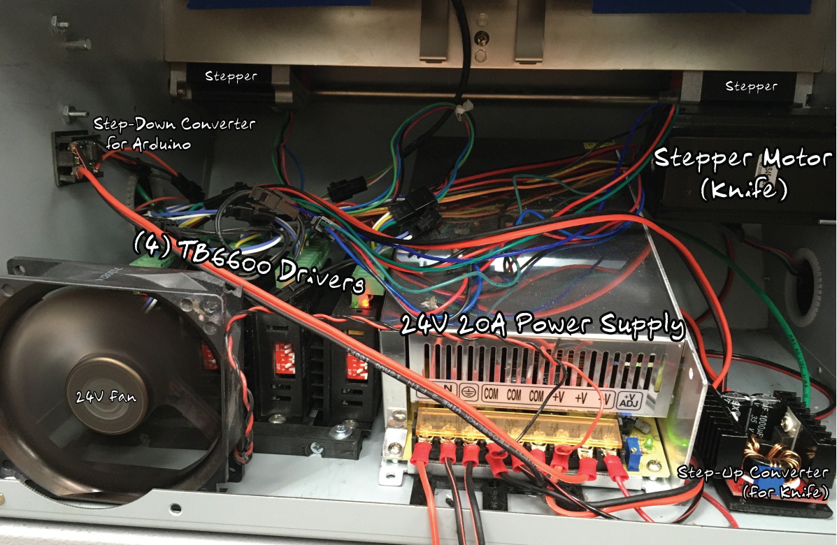
An Arduino Mega 2560 clone is used to control four TB6600 stepper motor drivers, with a common OLED display module installed where the original display went. The keypad next to the screen has been replaced with 10 arcade-style buttons soldered to a scrap of perfboard, though in the end [tommycoolman] covers them with a very professional looking printed vinyl sheet. There’s also a 24 V power supply onboard, with the expected assortment of step up and step down converters necessary to feed the various electronics their intended voltages.

In the end, [tommycoolman] estimates it took about $200 and 30 hours of work to get the card cutter up and running again. The argument could be made that the value of his time needs to be factored into the repair bill as well, but even still, it sounds like a bargain to us; these machines have a four-figure price tag on them when new.

Stories like this one are important reminders of the all wondrous things you can find hiding in the trash. Any time a machine like this can be rescued from the junkyard, it’s an accomplishment worthy of praise in our book.

What can you do with ferromagnetic PLA? [TheMixedSignal] used it to give new meaning to the term ‘musicians’ gear’. He’s made a proof of concept for a DIY tone generator, which is the same revolutionary system that made the Hammond organ sing.

Whereas the Hammond has one tonewheel per note, this project uses an Arduino to drive a stepper at varying speeds to produce different notes. Like we said, it’s a proof of concept. [TheMixedSignal] is proving that tonewheels can be printed, pickups can be wound at home, and together they will produce audible frequencies. The principle is otherwise the same — the protruding teeth of the gear induce changes in the magnetic field of the pickup.

[TheMixedSignal] fully intends to expand on this project by adding more tone wheels, trying different gear profiles, and replacing the stepper with a brushless motor. We can’t wait to hear him play “Karn Evil 9”. In the meantime, put on those cans and check out the demo/build video after the break.

We don’t have to tell you how great Hammond organs are for making music. But did you know they can also encode secret messages?

Via the Arduino blog.

Taking pictures in the 21st century is incredibly easy. So easy in fact that most people don’t even own a dedicated camera; from smartphones to door bells there are cameras built into nearly electronic device we own. So in this era of ubiquitous photography, you might think that a very slow and extremely low resolution camera wouldn’t be of interest. Under normal circumstances that’s probably true, but this single pixel camera built by [Tucker Shannon] is anything but normal.

At the heart of his unusual camera is the TCS34725 RGB color sensor from Adafruit which receives a tightly focused beam of incoming light by way of a 3D printed enclosure and a 3mm OD aluminum tube. This allows an Arduino Uno to determine the color of this tiny slice of light, making up a single pixel of the final color image. [Tucker] notes that you could even swap the color sensor out for a simple photocell if you don’t mind a black & white image at the end of the process.

In either event, once the light has been analyzed the sensor is repositioned autoturret-style by way of dual BYJ-48 stepper motors. This process continues on, spiraling outwards until the whole image is stitched together from these individual readings

Now compared to the camera in your phone, the resulting image might be a bit underwhelming. We’d say it’s a bit like looking at a digital picture on an 8 bit computer, but in truth even that might be overly generous. But even if it isn’t as crisp as modern eyes would like there’s no question that it’s certainly a recognizable image, which is all [Tucker] was shooting for.

Of course if your optical frugality is such that even this low-resolution camera is too sharp for your tastes, we’ve seen a similar concept  using a roof-mounted solar array.

Those just starting out in 3D printing often believe that their next major purchase after the printer will be a 3D scanner. If you’re going to get something that can print a three dimensional model, why not get something that can create said models from real-world objects? But the reality is that only a small percentage ever follow through with buying the scanner; primarily because they are notoriously expensive, but also because the scanned models often require a lot of cleanup work to be usable anyway.

While this project by [Travis Antoniello] won’t make it any easier to utilize scanned 3D models, it definitely makes them cheaper to acquire. So at least that’s half the battle. Consisting primarily of a stepper motor, an Arduino, and a EasyDriver controller, this is a project you might be able to assemble from the parts bin. Assuming you’ve got a pretty decent camera in there, anyway…

The general idea is to place a platform on the stepper motor, and have the Arduino rotate it 10 degrees at a time in front of a camera on a tripod. The camera is triggered by an IR LED on one of the Arduino’s digital pins, so that it takes a picture each time the platform rotates. There are configurable values to give the object time to settle down after rotation, and a delay to give the camera time to take the picture and get ready for the next one.

Once all the pictures have been taken, they are loaded into special software to perform what’s known as photogrammetry. By compiling all of the images together, the software is able to generate a fairly accurate 3D image. It might not have the resolution to make a 1:1 copy of a broken part, but it can help shave some modeling time when working with complex objects.

We’ve previously covered the use of photogrammetry to design 3D printed accessories, as well as a slightly different take on an automated turntable a few years ago. The process is still not too common, but the barriers to giving it a try on your own are at least getting lower.

Light painting: there’s something that never gets old about waving lights around in a long exposure photo. Whilst most light paintings are single shots, some artists painstakingly create frame-by-frame animations. This is pretty hard to do when moving a light around by hand: it’s mostly guesswork, as it’s difficult to see the results of your efforts until after the photo has been taken. But what if you could make the patterns really precise? What if you could model them in 3D?

[Josh Sheldon] has done just that, by creating a process which allows animations formed in Blender to be traced out in 3D as light paintings. An animation is created in Blender then each frame is automatically exported and traced out by an RGB LED on a 3D gantry. This project is the culmination of a lot of software, electronic and mechanical work, all coming together under tight tolerances, and [Josh]’s skill really shines.

The first step was to export the animations out of Blender. Thanks to its open source nature, Python Blender add-ons were written to create light paths and convert them into an efficient sequence that could be executed by the hardware. To accommodate smooth sliding camera movements during the animation, a motion controller add-on was also written.

The gantry which carried the main LED was hand-made. We’d have been tempted to buy a 3D printer and hack it for this purpose, but [Josh] did a fantastic job on the mechanical build, gaining a solidly constructed gantry with a large range. The driver electronics were also slickly executed, with custom rack-mount units created to integrate with the DragonFrame controller used for the animation.

The video ends on a call to action: due to moving out, [Josh] was unable to continue the project but has done much of the necessary legwork. We’d love to see this project continued, and it has been documented for anyone who wishes to do so. If you want to check out more of [Josh]’s work, we’ve previously written about that time he made an automatic hole puncher for music box spools.

Thanks for the tip, [Nick].

mechbox

Les Boites Mécaniques are a set of four automated boxes that produce music out of wood and metal. These experimental instruments enable anyone to explore the magic of making sound by pressing buttons on a remote, which activate each respective device to vibrate, knock, and rub materials.

The boxes were developed by Kogumi‘s Anatole Buttin and Yan Godat for educational electronic music workshops, and can be played either solo or in unison. There’s even a mode that allows users to control it all via MIDI notes on a computer.

In terms of hardware, each box is equipped with an Arduino Uno, a TLC59711 LED driver, step motors with AccelStepper library and a 3D-printed microstep driver.

Watch the video below to see how it all comes together to create a unique sound!

[Tim] was tired of compromising his portrait-oriented digital photos by shoehorning them into landscape-only frames. Unable to find a commercial solution, he built his own rotating digital photo frame from a 27″ LCD TV.

It uses a Raspi 3 to find [Tim]’s pictures on a giant SD card. He originally wanted to have the Pi pull pictures from Google Photos and display them randomly, but the API doesn’t work in that direction. Instead, a Python script looks at the pictures on the SD card and determines whether each is landscape or portrait-oriented. If a picture was taken in portrait-mode, the display will rotate 90 degrees. Rotation is handled with an Arduino, a stepper motor, and some 3D-printed herringbone gears. The first version was a bit noisy, so [Tim] re-printed the motor mount and the pinion gear out of flexible filament.

[Tim] designed the mount and frame himself and laser-cut the pieces out of birch plywood. We like that he accounted for the front-heaviness and that he covered the high voltage circuitry with acrylic to mitigate the risk of shock. All the code and design files are available on his project page. Make the jump to see a brief demonstration followed by a walk-through and stay for the six-minute slide show.


Filed under: Arduino Hacks, Raspberry Pi

In this three part video series we watch [Dirk Herrendoerfer] go from scraps to a nice 3D printed assembly as he iterates through the design of a pen plotter for making circuit boards.

[dana] mentioned [Dirk]’s work in the comments of this post which describes a different process. Many permanent markers stick to copper well enough to last through the chemical etching process. While hand drawing definitely produces some cool, organic-looking boards, for sharp lines and SMDs it gets a bit harder; to the point where it becomes advisable to just let a robot do it.

Of course, [Dirk] was aware of this fact of life. He just didn’t have a robot on hand. He did have some electronic detritus, fishing line, an Arduino, scrap wood, brass tubes, and determination.  The first version‘s frame consisted of wooden blocks set on their ends with holes drilled to accept brass rods. The carriage was protoboard and hot glue. Slightly larger brass tubing served as bushings and guide. As primitive as it was the plotter performed admirably, albeit slowly.

The second version was a mechanical improvement over the first, but largely the same. The software got a nice improvement. It worked better and had some speed to it.

The latest version has some fancy software upgrades; such as acceleration. The frame has gone from random bits of shop trash to a nicely refined 3D printed assembly. Even the steppers have been changed to the popular 28BYJ-48 series. All the files, software and hardware, are available on GitHub. The three videos are viewable after the break. It’s a great example of what a good hacker can put together for practically no money.


Filed under: Arduino Hacks, cnc hacks

[gocivici] threatened us with a tutorial on positional astronomy when we started reading his tutorial on a Arduino Powered Star Pointer and he delivered. We’d pick him to help us take the One Ring to Mordor; we’d never get lost and his threat-delivery-rate makes him less likely to pull a Boromir.

As we mentioned he starts off with a really succinct and well written tutorial on celestial coordinates that antiquity would have killed to have. If we were writing a bit of code to do our own positional astronomy system, this is the tab we’d have open. Incidentally, that’s exactly what he encourages those who have followed the tutorial to do.

The star pointer itself is a high powered green laser pointer (battery powered), 3D printed parts, and an amalgam of fourteen dollars of Chinese tech cruft. The project uses two Arduino clones to process serial commands and manage two 28byj-48 stepper motors. The 2nd Arduino clone was purely to supplement the digital pins of the first; we paused a bit at that, but then we realized that import arduinos have gotten so cheap they probably are more affordable than an I2C breakout board or stepper driver these days. The body was designed with a mixture of Tinkercad and something we’d not heard of, OpenJsCAD.

Once it’s all assembled and tested the only thing left to do is go outside with your contraption. After making sure that you’ve followed all the local regulations for not pointing lasers at airplanes, point the laser at the north star. After that you can plug in any star coordinate and the laser will swing towards it and track its location in the sky. Pretty cool.


Filed under: Arduino Hacks, cnc hacks, news, solar hacks


  • Newsletter

    Sign up for the PlanetArduino Newsletter, which delivers the most popular articles via e-mail to your inbox every week. Just fill in the information below and submit.

  • Like Us on Facebook