Posts | Comments

Planet Arduino

Archive for the ‘Stepper Motor’ Category

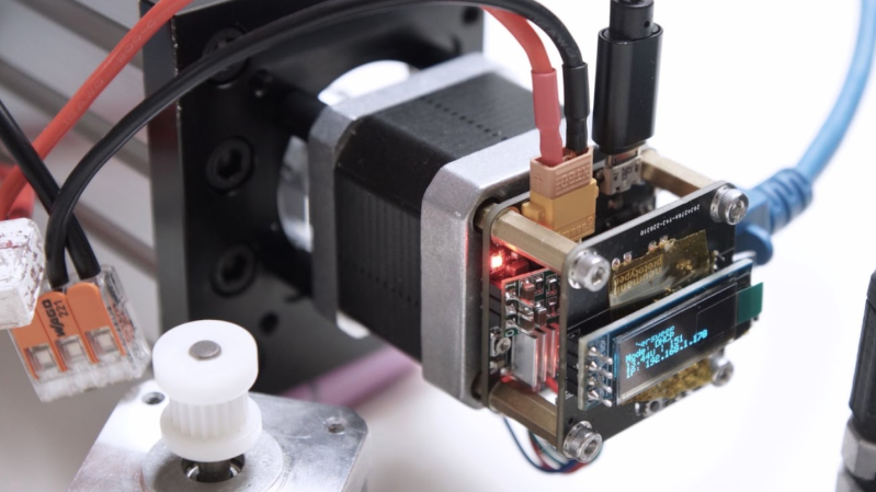
[Neumi] over on Hackaday.IO wanted a simple-to-use way to drive stepper motors, which could be quickly deployed in a wide variety of applications yet to be determined. The solution is named Ethersweep, and is a small PCB stack that sits on the rear of the common NEMA17-format stepper motor. The only physical connectivity, beside the motor, are ethernet and a power supply via the user friendly XT30 connector. The system can be closed loop, with both an end-stop input as well as an on-board AMS AS5600 magnetic rotary encoder (which senses the rotating magnetic field on the rear side of the motor assembly – clever!) giving the necessary feedback. Leveraging the Trinamic TMC2208 stepper motor driver gives Ethersweep silky smooth and quiet motor control, which could be very important for some applications. A rear-facing OLED display shows some useful debug information as well as the all important IP address that was assigned to the unit.

Control is performed with the ubiquitous ATMega328 microcontroller, with the Arduino software stack deployed, making uploading firmware a breeze. To that end, a USB port is also provided, hooked up to the uC with the cheap CP2102 USB bridge chip as per most Arduino-like designs. The thing that makes this build a little unusual is the ethernet port. The hardware side of things is taken care of with the Wiznet WS500 ethernet chip, which implements the MAC and PHY in a single device, needing only a few passives and a magjack to operate. The chip also handles the whole TCP/IP stack internally, so only needs an external SPI interface to talk to the host device.

Talking about firmware for a moment, to ease deployment, the network configuration is handled by DHCP, although some control over MAC address assignment is promised for the future. All control is via UDP over ethernet, and again the basic functionality is there, but some niceties such as motor synchronisation and state querying are again subject to further releases. Hardware design is implemented in KiCAD and FreeCAD, with Arduino covering the firmware and host control side in python. You can read all about it on the Ethersweep project GitHub, what is there not to like?

If you thought you’d seen this stepper-mounted driver setup before, you’d be correct, here’s a Hackaday Prize 2017 Entry for a CANBUS controlled driver. We also saw this on Dummy: the obscenely well made robot arm by [Zhihui Jun], which if you missed it, then do circle back and take a look, you won’t regret it!

The holidays always remind us of our favorite toys from when we were kids. Johnny Astro, an Erector set, and — of course — a Spirograph. [CraftDiaries] has an Arduino machine that isn’t quite a Spirograph, but it sure reminds us of one. The Arduino drives two stepper motors that connect to a pen that can create some interesting patterns.

The build uses a few parts that were laser cut, but they don’t look like they’d be hard to fabricate using conventional means or even 3D printing. The author even mentions you could make them out of cardboard or foamboard if you wanted to.

The electronics are straightforward with two stepper drivers. We couldn’t help but think that some of the old 3D printer motherboards we have laying around here could handle this very easily. However, in this project, the CPU is an ordinary UNO with a CNC shield to drive the motors.

Of course, the real trick is the software. Apparently, the different patterns come from the relationship between the delay between steps of the right motor and that of the left motor. There’s got to be some math behind that, but the patterns are certainly pretty.

If you prefer something that looks more like an actual Spirograph, grab a bag of Lego. Or try the Art-O-Matic.

Let’s face it — eating different colored candy like M&Ms or Skittles is just a little more fun if you sort your pile by color first. The not-fun part is having to do it by hand. [Jackofalltrades_] decided to tackle this time-worn problem for engineering class because it’s awesome and it satisfies the project’s requirement for sensing, actuation, and autonomous sequencing. We’d venture to guess that it satisfies [Jackofalltrades_]’ need for chocolate, too.

Here’s how it works: one by one, M&Ms are selected, pulled into a dark chamber for color inspection, and then dispensed into the proper cubby based on the result. [Jackofalltrades_] lived up to their handle and built a color-detecting setup out of an RGB LED and light-dependent resistor. The RGB LED shines red, then, green, then blue at full brightness, and takes a voltage reading from the photocell to figure out the candy’s color. At the beginning, the machine needs one of each color to read in and store as references. Then it can sort the whole bag, comparing each M&M to the reference values and updating them with each new M&M to create a sort of rolling average.

We love the beautiful and compact design of this machine, which was built to maximize the 3D printer as one of the few available tools. The mechanical design is particularly elegant. It cleverly uses stepper-driven rotation and only needs one part to do most of the entire process of isolating each one, passing it into the darkness chamber for color inspection, and then dispensing it into the right section of the jar below. Be sure to check out the demo after the break.

Need a next-level sorter? Here’s one that locates and separates the holy grail of candy-coated chocolate — peanut M&Ms that didn’t get a peanut.

If you’ve ever watched one of those high production value YouTube videos and wondered how they’re able to get those smooth shots where the camera seems to be spinning around an object, you were probably looking at the product of an motorized camera motion system. There’s no question these rigs can produce visually striking shots, but their high cost usually keeps them out of the hands of us lowly hackers.

Unless of course you do like [Andy], and build your own. The latest version of this impressive rig features the ability to continuously rotate thanks to commercial 12-wire slip rings, with optical endstops so the machine can still be homed at the beginning of a move. An onboard Raspberry Pi and Arduino Uno are responsible for controlling the stepper motors, the configuration of which ends up being reminiscent of a standard 3D printer.

The MQTT remote can hold a phone for live video.

The software [Andy] has come up with lets him synchronize the camera rig with a small rotating platform he built, which allows for even more complex shots as demonstrated in the video below. It also supports a very slick MQTT-enabled remote controller that he built as a previous project, which makes taking direct control over the camera and monitoring its status much easier.

Want to add a little polish to your own project videos? [Andy] has released all of the files and information you’d need to build your own version of his motion control rig, though we wouldn’t blame you for feeling a bit intimidated by this one. It might not be the most elaborate camera motion control system we’ve seen, but it’s certainly up there. If you just want an overhead video and don’t need those fancy tracking shots, perhaps a modified VESA arm would fit the bill.

Playing the guitar requires speed, strength, and dexterity in both hands. Depending on your mobility level, rocking out with your axe might be impossible unless you could somehow hold down the strings and have a robot do the strumming for you.

[Jacob Stambaugh]’s Auto Strummer uses six lighted buttons to tell the hidden internal pick which string(s) to strum, which it does with the help of an Arduino Pro Mini and a stepper motor. If two or more buttons are pressed, all the strings between the outermost pair selected will be strummed. That little golden knob near the top is a pot that controls the strumming tempo.

[Jacob]’s impressive 3D-printed enclosure attaches to the guitar with a pair of spring-loaded clamps that grasp the edge of the sound hole. But don’t fret — there’s plenty of foam padding under every point that touches the soundboard.

We were worried that the enclosure would block or muffle the sound, even though it sits about an inch above the hole. But as you can hear in the video after the break, that doesn’t seem to be the case — it sounds fantastic.

Never touched a real guitar, but love to play Guitar Hero? There’s a robot for that, too.

In theory, there’s isn’t much to building a CNC machine. Hook a bit to a motor and move the motor around with some lead screws and stepper motors. Easy. But, of course, the devil is in the details. [DAZ] made a nice-looking and inexpensive rig that probably isn’t the most precise CNC in the world, but it looks like it does a good enough job and he claims he spent about $50 on it. The video below shows some of the work it has done, and it doesn’t look bad.

This isn’t a rainy afternoon project. You’ll need to cut some wood and 3D print many parts. The drives use M8 threaded rod. Electronics is just an Arduino running standard software.

The steppers looked pretty light duty, and we wondered if it would have been worthwhile to trade them out for beefier ones instead of modifying the ones used for bipolar operation. Still, the results did look good for $50. The 775 spindle is another place you could probably spend a little more and get something better. Non-printed linear rails, and a better screw? The point is that you’ve got a basis to build from.

We’ve seen cheap CNCs made from scrap before. If you decide an Arduino is too low-powered for your CNC, try going 32-bit.

It’s 2021. Everyone and their mother is filming themselves doing stuff, and a lot of it is super cool content. But since most of us have to also work the video capture devices ourselves, it can be difficult to make compelling footage with a single, stationary overhead view, especially when there are a lot of steps involved. A slider rig is a good start, but the ability to move the camera in three dimensions programmatically is really where it’s at.

[KronBjorn]’s excellent automated overhead camera assistant runs on an Arduino Mega and is operated by typing commands in the serial monitor. It can pan ±20° from straight down and moves in three axes on NEMA-17 stepper motors. It moves really smoothly, which you can see in the videos after the break. The plastic-minimal design is interesting and reminds us a bit of an ophthalmoscope — that’s that main rig at the eye doctor. There’s only one thing that would make this better, and that’s a dedicated macro pad.

If you want to build your own, you’re in luck — there’s quite a lot of detail to this project, including a complete BOM, all the STLs, code, and even assembly videos of the 3D-printed parts and the electronics. Slide past the break to check out a couple of brief demo videos.

Not enough room for a setup like this one? Try the pantograph version.

What could be more terrifying than ghosts, goblins, or clowns? How about a shapeless pile of fright on your bedroom floor that only moves when you’re not looking at it? That’s the idea behind [Sciencish]’s nightmare robot, which is lurking after the break. The Minecraft spider outfit is just a Halloween costume.

In this case, “looking at it” equates to you shining a flashlight on it, trying to figure out what’s under the pile of clothes. But here’s the thing — it never moves when light is shining on it. It quickly figures out the direction of the light source and lies in wait. After you give up and turn out the flashlight, it spins around to where the light was and starts moving in that direction.

The brains of this operation is an Arduino Uno, four light-dependent resistors, and a little bit of trigonometry to find the direction of the light source. The robot itself uses two steppers and printed herringbone gears for locomotion. Its chassis has holes in it that accept filament or wire to make a cage that serves two purposes — it makes the robot into more of an amorphous blob under the clothes, and it helps keep clothes from getting twisted up in the wheels. Check out the demo and build video after the break, because this thing is freaky fast and completely creepy.

While we usually see a candy-dispensing machine or two every Halloween, this year has been more about remote delivery systems. Don’t just leave sandwich bags full of fun size candy bars all over your porch, build a candy cannon or a spooky slide instead.

Via r/duino

If you have any kind of business, chances are it involves stickers at some point in the process. More accurately it involves you peeling the backs off of sticker after sticker, slowly wasting time and working your way toward a repetitive stress injury. Why do that to yourself when you could have a machine do it for you?

That’s exactly the thinking behind [Mr Innovative]’s automatic label dispensing machine. All he has to do is load up the roll of labels, dial in the length of each label, and away the machine goes, advancing and dispensing and taking up the empty paper all at once. In fact, that’s how it works: the take-up reel is on the shaft of a NEMA-17 stepper motor, which gets its instructions from an Arduino Nano and an A4988 motor driver. Our favorite part is the IR sensor located underneath the sticker that’s ready to take — the machine doesn’t feed another until it senses that you’ve taken the previous sticker. We stuck the demo and build video after the break.

Our other favorite thing about this build is that [Mr Innovative] seems to have used the same PCB as his freaky fast bobbin winder.

We’ve all seen videos of blisteringly fast SCARA arms working on assembly lines, and more than a few of us have fantasied about having that same kind of technology for the home shop. Unfortunately, while the prices for things like 3D printers and oscilloscopes have dropped lower than what many would have believed possible a decade ago, high-performance robotics are still too pricey for the home player.

Unless of course, you’re willing to build it yourself. The PyBot designed by [jjRobots] is an open source robotic arm that should be well within the means of the average hardware hacker. One could argue that this is a project made entirely possible by desktop 3D printing; as not only are most of the structural components printed, but most of the mechanical elements are common 3D printer parts. Smooth rods, linear bearings, lead screws, and NEMA 17 motors are all exceptionally cheap these days thanks to the innumerable 3D printer kits that make use of them.

A custom control board keeps the wiring tight.

Those who’ve researched similar projects might notice that the design of this arm has clearly been influenced by the Mostly Printed SCARA (MPSCARA). But while that robot was designed to carry an extruder and act as a 3D printer, [jjRobots] intends for the PyBot to be more of a general purpose platform. By default it features a simple gripper, but that can easily be changed out for whatever tool or gadget you have in mind.

In the base of the arm is a custom control board that combines an Arduino M0, an ESP8266, and a trio of stepper motor drivers. But if you wanted to build your own version from the parts bin, you could certainly wire up all the principle components manually. As the name implies, the PyBot is controlled by Python tools running on the computer, so it should be relatively easy to get this capable arm to do your bidding.

We’ve seen some impressive 3D printed robotic arms over the years, but the simplicity of the PyBot is particularly compelling. This looks like something that you could reasonably assemble and program over a weekend or two, and then put to work in your ad-hoc PPE factory.


  • Newsletter

    Sign up for the PlanetArduino Newsletter, which delivers the most popular articles via e-mail to your inbox every week. Just fill in the information below and submit.

  • Like Us on Facebook