Posts | Comments

Planet Arduino

Archive for the ‘flex sensor’ Category

In order to build wearables that react to movement, most people tend to reach for accelerometers, gyroscopes, and flex sensors. But due to their higher cost, one of teacher Gord Payne’s students wanted to create a low-cost alternative that could be easily sourced and integrated into projects.

A typical glove with finger movement tracking normally incorporates flexible strips, which vary in resistance based on the extent of their deviation from the starting angle. By reading this value with an Arduino board’s analog-to-digital converter (ADC) and mapping the resistance with a formula, the total angle can be found with decent accuracy. The student’s idea, however, substituted this special material for a flexible tube that has an LED on one end and a light-dependent resistor (LDR) on the other. When kept at the starting position, all of the light from the LED is able to hit the LDR, and any bends introduced from bending the tube cause less light to reach the other side.

After performing a few test runs to determine the exact mapping of resistance values coming from the LDR compared to the angle of the finger, the student’s code could accurately calculate the angle based on a simple formula. To demonstrate this project, a servo was connected to the microcontroller and made to mimic how the finger is moved.

More information can be found here on Payne’s Hackaday.io write-up

The post Substituting a flex sensor for an inexpensive light-dependent resistor appeared first on Arduino Blog.

You can turn on an LED with a button or switch, but what about by bending your finger? Willpower Studios’ textile flex sensor, dubbed Finger Bend, presents a method for such an interface.

Inside the custom sleeve is a piece of piezoresistive stretch fabric, which is attached by copper threads to an Arduino Nano’s analog input pin. When a finger is curled, the light is then turned on and turned off again when straightened.

While an LED is interesting, this concept could be taken much further, perhaps using multiple digits for more intricate control. Details and code for the project is available in Willpower Studios’ write-up.

The post Finger Bend is a DIY textile flex sensor appeared first on Arduino Blog.

If you’ve spent any serious time in libraries, you’ve probably noticed that they attract people who want or need to be alone without being isolated. In this space, a kind of silent community is formed. This phenomenon was the inspiration [MoonAnchor23] needed to build a network of connected house plants for a course on physical interaction and realization. But you won’t find these plants unleashing their dry wit on twitter. They only talk to each other and to nearby humans.

No living plants were harmed during this project—the leaves likely wouldn’t let much light through, anyway. The plants are each equipped with a strip of addressable RGB LEDs and a flex sensor controlled by an Arduino Uno. Both are hot glued to the undersides of the leaves and hidden with green tape. By default, the plants are set to give ambient light. But if someone strokes the leaf with the flex sensor, it sends a secret message to the other plant that induces light patterns.

Right now, the plants communicate over Bluetooth using an OpenFrameworks server on a local PC. Eventually, the plan is use a master-slave configuration so the plants can be farther apart. Stroke that mouse button to see a brief demo video after the break. [MoonAnchor23] also built LED mushroom clusters out of silicone and cling wrap using a structural soldering method by [DIY Perks] that’s also after the break. These work similarly but use force-sensing resistors instead of flex-sensing.

Networking several plants together could get expensive pretty quickly, but DIY flex sensors would help keep the BOM costs down.

Nov
23

Sensing A Bend With A Flex Sensor + Arduino

arduino, flex, flex sensor, Sensor, tutorials Comments Off on Sensing A Bend With A Flex Sensor + Arduino 

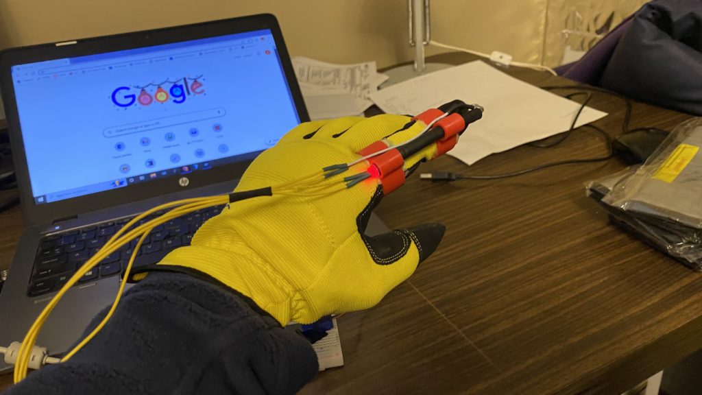
We spend so much time talking about sensing things less mechanical, that is is easy to forget the accelerometer isnt the only part in town. The flex sensor is one of those parts often overlooked by the advanced user. But what if you need to check if something bent? Like a finger, or a doll arm. (A lot of toy prototypes seem to have this need).

Anytime you need to detect a flex, or bend, a flex sensor is probably the part for you. They come in a few different sizes ( small, large).

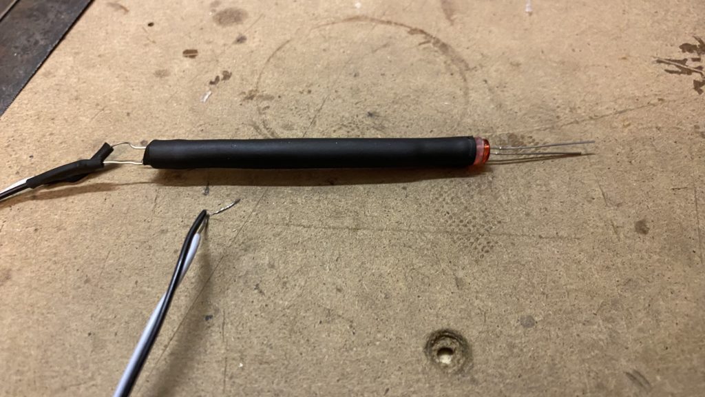
The flex sensor is basically a variable resistor that reacts to bends. Unbent it measures about 22KΩ, to 40KΩ when bend 180º. Note that the bend is only detected in one direction and the reading can be a bit shaky, so you will have best results detecting changes of at least 10º.

Also, make sure you don’t bend the sensor at the base as it wont register as a change, and could break the leads. I always tape some thick board to the base of it to make it wont bend there.

Hooking it up, and why

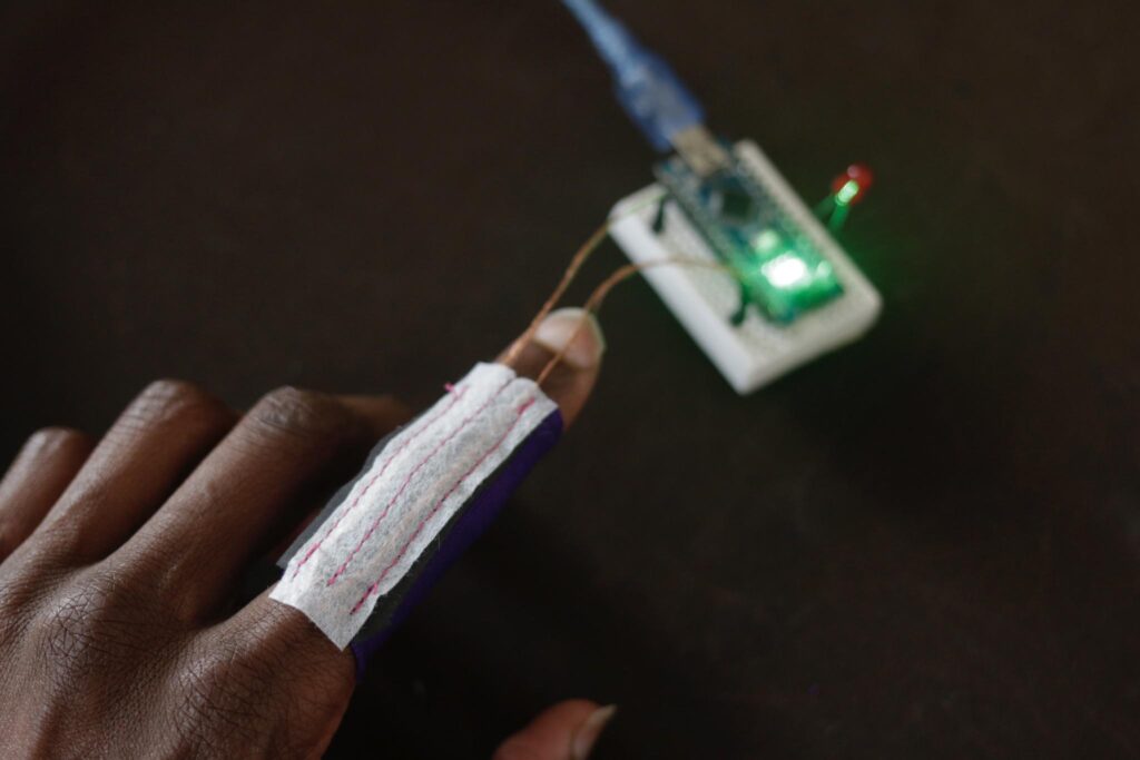
The flex sensor changes its resistance when flexed so we can measure that change using one of the Arduino’s analog pins. But to do that we need a fixed resistor (not changing) that we can use for that comparison (We are using a 22K resistor). This is called a voltage divider and divides the 5v between the flex sensor and the resistor.

The analog read on your arduino is basically a voltage meter. at 5V (its max) it would read 1023, and at 0v it read 0. So we can measure how much voltage is on the flex sensor using the analogRead and we have our reading.

The amount of that 5V that each part gets is proportional to its resistance. So if the the flex sensor and the resistor have the same resistance, the 5V is split evenly (2.5V) to each part. (analog reading of 512)

Just pretend that the the sensor was reading only 1.1K of resistance, the 22K resistor is going to soak up 20 times as much of that 5V. So the flex sensor would only get .23V. (analog reading of 46)

And if we roll the flex sensor around a tibe, the flex sensor may be 40K or resistance, so the flex sensor will soak up 1.8 times as much of that 5V as the 22K resistor. So the flex sensor would get 3V. (analog reading of 614)

Code

The arduino code for this just could not be easier. We are adding some serial prints and delays to it just so you can easily see the readings, but they dont need to be there if you dont need them.

In my tests I was getting a reading on the arduino between 512, and 614. So the range isnt the best. But using the map() function, you can convert that to a larger range.

int flexSensorPin = A0; //analog pin 0

void setup(){
  Serial.begin(9600);
}

void loop(){
  int flexSensorReading = analogRead(flexSensorPin); 

  Serial.println(flexSensorReading);


  //In my tests I was getting a reading on the arduino between 512, and 614. 
  //Using map(), you can convert that to a larger range like 0-100.
  int flex0to100 = map(flexSensorReading, 512, 614, 0, 100);
  Serial.println(flex0to100);

  delay(250); //just here to slow down the output for easier reading
}
Unless otherwise stated, this code is released under the MIT License – Please use, change and share it.


  • Newsletter

    Sign up for the PlanetArduino Newsletter, which delivers the most popular articles via e-mail to your inbox every week. Just fill in the information below and submit.

  • Like Us on Facebook