Posts | Comments

Planet Arduino

Archive for the ‘tool hacks’ Category

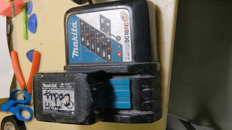
Lots of things beep these days. Washing machines, microwaves, fridge — even drill battery chargers. If you’re on Team Makita, it turns out you can actually change the melody of your charger’s beep, thanks to a project from [Real-Time-Kodi].

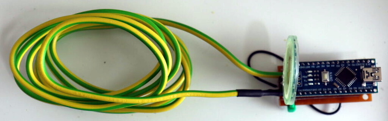
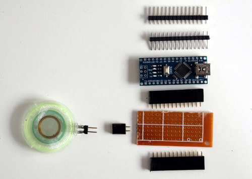
The hack is for the Makita DR18RC charger, and the implementation of the hack is kind of amusing. [Real-Time-Kodi] starts by cutting the trace to the buzzer inside the charger. Then, an Arduino is installed inside the charger, hooked up to the buzzer itself and the original line that was controlling it. When it detects the charger trying to activate the buzzer, it uses this as a trigger to play its own melody on the charger instead. The Arduino also monitors the LEDs on the charger in order to determine the current charge state, and play the appropriate jingle for the situation.

It’s an amusing hack, and one that could certainly confuse the heck out of anyone expecting the regular tones out of their Makita charger. It also shows that the simple ways work, too — there was no need to dump any firmware or decompile any code.

Thermal cameras can cost well into the five-figure range if you’re buying high-resolution models with good feature sets. New models can be so advanced that their export and use is heavily controlled by certain countries, including the USA. If you just want to tinker at the low end, though, you don’t have to spend a lot of scratch. You can even build yourself something simple based on an Arduino Uno!

The build uses Panasonic’s cheap “Grid-EYE” infrared array as the thermal sensor, in this case, a model with an 8×8 array of thermopiles. It’s not going to get you any fancy images, especially at long range, but you can use it to get a very blocky kind of Predator-vision of the thermal radiation environment. It’s a simple matter of hooking up the Grid-EYE sensor to the Arduino Uno over I2C, and then spitting out the sensor’s data in a nice visual form on a cheap TFT screen.

It’s a great introduction to the world of thermal imaging. There’s no better way to learn how something works by building a working example yourself. We’ve featured a few similar projects before, too; it’s all thanks to the fact that thermal sensors are getting cheaper and more accessible than ever!

Coil winders are a popular project because doing the deed manually can be an incredibly tedious and time consuming task. After building one such rig, [Pisces Printing] wanted to find even further time savings, and thus designed an improved, faster version.

At it’s heart, it’s a straightforward design, using a linear rail and a leadscrew driven by a stepper motor. Control is via an Arduino Nano, with a few push buttons and a 16 x 2 LCD display for user feedback.

Often, completing a first build will reveal all manner of limitations and drawbacks of a design. In this case, the original winder was improved upon with faster stepper motors to cut the time it took to wind a coil. A redesigned PCB also specified a better buck converter power supply to avoid overheating issues of the initial design. A three-jaw lathe-style chuck was also 3D printed for the build to allow easy fixing of a coil bobbin.

Designing custom tools can be highly satisfying in and of itself, beyond the productivity gains they offer. Video after the break.

"The Great Resistor" color code illumination project

With surface-mount components quickly becoming the norm, even for homebrew hardware, the resistor color-code can sometimes feel a bit old-hat. However, anybody who has ever tried to identify a random through-hole resistor from a pile of assorted values will know that it’s still a handy skill to have up your sleeve. With this in mind, [j] decided to super-size the color-code with “The Great Resistor”.

Resistor color code from Wikipedia with white background
How the resistor color-code bands work

At the heart of the project is an Arduino Nano clone and a potential divider that measures the resistance of the test resistor against a known fixed value. Using the 16-bit ADC, the range of measurable values is theoretically 0 Ω to 15 MΩ, but there are some remaining issues with electrical noise that currently limit the practical range to between 100 Ω and 2 MΩ.

[j] is measuring the supply voltage to help counteract the noise, but intends to move to an oversampling/averaging method to improve the results in the next iteration.

The measured value is shown on the OLED display at the front, and in resistor color-code on an enormous symbolic resistor lit by WS2812 RGB LEDs behind.

Inside view of the great resistor showing WS2812 LEDs and baffle plates
Inside The Great Resistor, the LEDs and baffle plates make the magic work

Precision aside, the project looks very impressive and we like the way the giant resistor has been constructed. It would look great at a science show or a demonstration. We’re sure that the noise issues can be ironed out, and we’d encourage any readers with experience in this area to offer [j] some tips in the comments below. There’s a video after the break of The Great Resistor being put through its paces!

If you want to know more about the history of the resistor color code bands, then we have you covered.  Alternatively, how about reading the color code directly with computer vision?

The hacking life is not without its challenges, and chief among these is the tendency to always be in acquisition mode. When we come across a great deal on bulk equipment, or see a chance to rescue some obscure gear from the e-waste stream, we generally pounce on it, regardless of the advisability.

We imagine this is why [Nathan] ended up with a hoard of PS/2 keyboards. Seriously, there are like thousands of the things. And rather than lug a computer to them for testing, [Nathan] put together this handy Arduino-based portable tester to see which keyboards still have some life left in them. The video below goes into detail on the build, but the basics are pretty simple — an Arduino, a 16×2 LCD display, and a few bits and bobs to run it off a LiPo pack and charge it up. Plus, of course, a PS/2 jack to plug in a keyboard and power it up. Interestingly, the 16×2 display is an old Parallax unit, from the days when RadioShack still existed and sold their stuff. That required a little effort to get it working with the Arduino, but in the end it works like a charm — plug in a keyboard and whatever you type shows up on the screen.

Of course, it’s hard to look at something like this, and that mountain of keyboards in the background, and not scheme up ways to really automate the whole test process. Perhaps an old 3D printer with a stylus mounted where the hot end would go could press each key in turn while the tester output is recorded — something like this Wordle-bot, but on a keyboard scale. That kind of goes against [Nathan]’s portability goal, but it’s still fun to think about.

There was a time when people like us might own a tube tester and even if you didn’t, you probably knew which drug store had a tube testing machine you could use for free. We aren’t sure that’s a testament to capitalistic ingenuity or an inditement of tube reliability — maybe both. As [Usagi] has been working on some tube-based projects, he decided he needed a tester so he built one. You can see the results in the video, below.

The tester only uses 24V, but for the projects he’s building, that’s close to the operation in the real circuits. He does have a traditional tube tester, but it uses 100s of volts which is a different operating regime.

The bulk of the circuit is creating the voltages required, including a 555 charge pump to generate around -10V. The tube is wired up in a particular configuration and the Arduino makes a few measurements while changing the operating bias conditions. The converter goes through a voltage divider so the maximum 24 volts won’t overload the Arduino.

Grabbing the data into a spreadsheet allowed some curve tracing which looked useful for matching. However, as [Usagi] points out, the tester is very specific to his application. He has plans to maybe make a more general-purpose tube tester.

One of the problems with a truly general-purpose tube tester is connecting to the different pinouts. Punched cards offered one answer. If you don’t remember tube testers in drug stores, you might find that TV repair, at one time, was a big business.

Small portable soldering irons are all the rage so [electronoobs] decided to build one on his own. While the design isn’t quite as sleek as a commercial unit, considering it holds its own batteries, it looks pretty good.

Of course, the question is: does it work? You can see in the video below that it does, melting solder in about ten seconds. The weight is about 100 g, so it should be very comfortable to use.

A small display shows operational parameters. We also liked the threaded mount for the tips. The tips need about 4 A from the battery which results in a 15 W iron. However, the tips don’t have a built-in thermocouple, so you can’t exactly temperature control the tip.

There was a bit of a problem with undervoltage detection, so you do need to be prepared to remove the battery manually if the voltage drops too low. This is somewhat painful, and we might have considered wiring a physical power switch to avoid having to open the 3D-printed case too often.

On the PCB is an Arduino, a MOSFET, and some instrumentation to monitor the battery current and the tip resistance. Naturally, you could do what you like with the firmware to make any number of customizations.

While the iron looks a little like a TS-100, that iron doesn’t contain batteries, so you have to carry an external supply or a battery. But there are commercial irons with batteries. Of course, there have been other similar projects, but we like the looks and expandability of this one.

We’ve all found ourselves swimming amongst too many similar-looking USB cables over the years. Some have all the conductors and functionality, some are weird power-only oddballs, and some charge our phones quickly while others don’t. It’s a huge headache and one that [TechKiwiGadgets] hopes to solve with the Arduino Cable Tracer.

The tracer works with USB-A, Mini-USB, Micro-USB, and USB-C cables to determine whether connections are broken or not and also to identify wiring configurations. It’s built around the Arduino Mega 2560, which is ideal for providing a huge amount of GPIO pins that are perfect for such a purpose. Probing results are displayed upon the 2.8″ TFT LCD display that makes it easy to figure out which cables do what.

It’s a tidy build, and one that we could imagine would be very useful for getting a quick go/no-go status on any cables dug out of a junk box somewhere. Just remember to WIDLARIZE any bad cables you find so they never trouble you again. Video after the break.

Unable to account for the strange glitches he was seeing on his DIY CNC router, [Daniël Van Den Berg]  wondered if his electronics might be suffering from some form of electromagnetic interference (EMI). So he did what any good hacker would do, and rummaged through the parts bin to build an impromptu EMI detector.

[Daniël] is quick to point out that he’s not an electrical engineer, and makes no guarantees about the accuracy of his tossed together gadget. But it does seem to work well enough in his testing that he’s able to identify particularly “noisy” electronic components, so it’s probably worth putting one together just to hear what your hardware is pumping into the environment.

The hardware here is very simple, [Daniël] just attached a coil of solid copper wire to one of the analog pins on an Arduino Nano with a resistor, and hung a speaker off of one of the digital pins. From there, it just took a few lines of code to read the voltage in the coil and convert that into a tone for the speaker. The basic idea is that a strong alternating magnetic field will set up voltage fluctuations in the coil large enough for the Arduino’s ADC to read.

If you’re looking for a bit more insight into what kind of interference your electronic creations might be putting out, [Alex Whittimore] gave a fantastic presentation during the 2020 Hackaday Remoticon about performing RF debugging using a cheap RTL-SDR dongle.


  • Newsletter

    Sign up for the PlanetArduino Newsletter, which delivers the most popular articles via e-mail to your inbox every week. Just fill in the information below and submit.

  • Like Us on Facebook