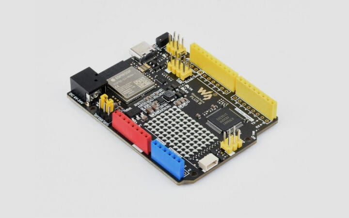
Arduino board clones have been around for many years, but I don’t think I have ever seen clones of the new Renesas-based Arduino boards so far. Waveshare changes that with the R7FA4 PLUS A that clones with Arduino UNO R4 Minima, and the R7FA4 PLUS B board duplicating the Arduino UNO R4 WiFi. The Waveshare boards are not 100% clones with some small differences in the PCB layout, support for 5V and 3.3V shields, an additional 6-pin “power output header” with 5V, 3.3V, and GND signals, and a USB communication jumper to select between the Espressif ESP32-S3 and Renesas RA4M1 microcontrollers. Waveshare R7FA4 PLUS A and B specifications: Microcontroller – Renesas RA4M1 Arm Cortex-M4F MCU @ 48 MHz with 32KB SRAM, 256KB flash Wireless (B model only) – ESP32-S3-MINI-1 module based on ESP32-S3 dual-core Xtensa LX7 microcontroller with 512KB SRAM, 384KB ROM, WiFi 4 and Bluetooth 5.0 connectivity, PCB antenna [...]
At the heart of the board is an ATmega328 clocked at 8MHz to reduce power consumption and fused to drop out at 1.7V. The radio module is a HopeRF RFM69C which as supplied is a little bit too big for the AA form factor so [Johan] has carefully filed away the edge of the PCB to make it fit. Enough room is left within the shape of an AA cell for a couple of DS18B20 temperature sensors and an indicator LED. He provides a handy buyer’s guide to the different versions of a 3xAA box with a lid, and all the files associated with the project are available in his GitHub repository.
Especially with the onboard radio module we can see that the AADuino board could be a very useful piece of kit. Perhaps for instance it could be used as a very low power self-contained UKHASnet node.
We’ve featured quite a few Arduino clones over the years that try to break the size mould in some way. This stripboard Arduino almost but not quite equals the AAduino’s size, as does this PCB version barely wider than the DIP package of its processor. But the AADuino is a bit different, in that it’s a ready-made form factor for putting out in the field rather than just another breadboard device. And we like that.
There are some standard components that have been so continuously refined as to have become if not perfect then about as good as they’re going to get. Take the Arduino Uno for instance, and compare it with its ancestor from a decade ago. They are ostensibly the same board and they are compatible with each other, yet the Uno and its modern clones have more processing power, memory and storage, a USB interface rather than serial, and a host of small component changes to make them better and cheaper.
You’d think that just another Arduino clone couldn’t bring much to the table then. And you’d be right in a broad sense, just what is there left to improve?
[Clovis Fritzen] has an idea for an Arduino clone that’s worth a second look. It’s not an amazing hardware mod that’ll set the Arduino world on fire, instead it’s a very simple design feature. He’s created an Arduino that mounts vertically on a single row of pins. Why might you find that attractive, you ask? A SIL vertical Arduino takes up a lot less breadboard space than one of the existing DIL Arduinos. A simple idea, yet one that is very useful if you find yourself running out of breadboard.
[Clovis] took the circuit of an Arduino Uno and simplified it by removing the USB interface, so this board has to be programmed through its ICSP header. And he’s made it a through-hole board for easy construction by those wary of SMD soldering. The resulting board files can all be found on GitHub.
Every now and then along comes a hack so simple, obvious, and useful that it makes you wonder just why you didn’t think of it yourself. Many of us will have used a DIL Arduino and probably found ourselves running out of breadboard space. This board probably won’t change the world, but it could at least make life easier in a small way for some of us who tinker with microcontrollers.
This is just the latest of many Arduino clones to find its way onto these pages. In 2013 we asked why the world needed more when featuring one made as a PCB design exercise. There’s even a Hackaday version called the HaDuino developed by [Brian Benchoff]. But while it’s true that Yet Another Vanilla Arduino Clone brings nothing to the table, that should not preclude people from taking the Arduino and hacking it. Every once in a while something useful like this project will come from it, and that can only be a benefit to our community.
We’ve featured loads of IR Arduino projects and they are all exciting and unique. The projects spring from a specific need or problem where a custom infrared remote control is the solution. [Rick’s] double feature we’re sharing in this article is no exception, but what is interesting and different about [Rick’s] projects is his careful and deliberate tutorial delivery on how to copy infrared remote codes, store the codes with a flavor of Arduino and then either transmit or receive the codes to control devices.
In the case of his space heater an Arduino was used to record and later retransmit the “power on” IR code to the heater before he awakes on a cold morning. This way his room is toasty warm before he has to climb out from under the covers, which has the added benefit of saving the cost of running the heater all night. Brilliant idea if you don’t have a programmable heating system. Maybe he will add a temperature sensor someday so it doesn’t have to run on strictly time.
A more complicated problem was controlling DVD playback software on his computer remotely. [Rick] says he sits at a distance when watching DVDs on his computer but his computer doesn’t have a remote control like a normal TV. Arduino to the rescue again! But this time he pulls out a Teensyduino because of its added feature of being able to emulate a keyboard and of course the computer DVD playback software accepts keyboard commands. Once again he used the “IRremote.h” library to record certain button codes from an old remote control before adding the retrieved codes to a Teensyduino setup and programmed to receive and decode the remote’s IR signals. The Teensyduino then maps the IR codes to known keyboard shortcuts and transmits the simulated keyboard shortcut commands to the computer via its USB cable where the DVD playback software recognizes the key commands.
As always [Rick] shares all his libraries and sketches on his blog so follow the above links to download the files. You will not miss a single step if you follow his excellent videos below. Plus, here are some other ways and other tools for using an IR remote with your Arduino and cloning an infrared remote.
arduino, arduino hacks, cloneComments Off on Another Arduino clone is the last thing the world needs
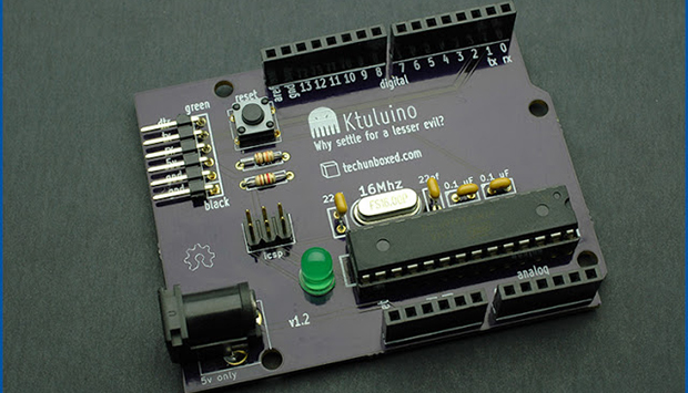
One might think the last thing the world needs is for The Great Old Ones to rise from their near-death sleep deep in the Pacific ocean, and begin again their reign over Earth. Actually, the last thing the world needs is another Arduino clone. Here’s this one. Fittingly, it’s called the Ktuluino.
Actually, this isn’t yet another attempt to build an Arduino clone that adds nothing to existing designs; it’s just [Jeff]‘s attempt at PCB design. He needed something to practice on, so why not something that ends in -uino?
The board is just about as simple as Arduinos come – an ATMega328P is the brains of the outfit and also the most expensive component, closely followed by either the power jack or the header pins. As an exercise in PCB design, we’ll give this a thumbs up, but this could also be used for an ‘introduction to soldering’ workshop at a hackerspace, or alternatively a coaster.
In this article we review the “Magpie” Arduino Uno-compatible board from Little Bird Electronics.
Introduction
Finally I’m back at the office and have a pile of things to write about. Starting with the subject of this review – the “Magpie” board from Little Bird Electronics in Australia. It seems that a new Arduino-compatible board enters the market every week, thanks to the open-source nature of the platform and the availability of rapid manufacturing. However the Magpie isn’t just any old Arduino Uno knock-off, it has something which helps it stand out from the crowd – status LEDs on every digital and analogue I/O pin. You can see them between the stacking header sockets and the silk-screen labels. For example:
and for the curious, the bottom of the Magpie:
At first glance you might think “why’d they bother doing that? I could just wire up some LEDs myself”. True. However having them on the board speeds up the debugging process as you can see when an output is HIGH or LOW – and in the case of an input pin, whether a current is present or not. For the curious the LEDs are each controlled by a 2N7002 MOSFET with the gate connected to the I/O pin, for example:
An LED will illuminate as long as the gate voltage is higher than the threshold voltage – no matter the status of the particular I/O pin. And if an I/O pin is left floating it may trigger the LED if the threshold voltage is exceeded at the gate. Therefore when using the Magpie it would be a good idea to set all the pins to LOW that aren’t required for your particular sketch. Even if you remove and reapply power the floating will still be prevalent, and indicated visually – for example:
Nevertheless you can sort that out in void setup(), and then the benefits of the LEDs become apparent. Consider the following quick demonstration sketch:
// LBE Magpie board LED demo - John Boxall 18 March 2013
// usual blink delay period
int d=100;
void setup()
{
 // digital pins to outputs
 for (int a=0; a<14; a++)
 {
 pinMode(a, OUTPUT);
 }
 pinMode(A0, OUTPUT);
 pinMode(A1, OUTPUT);
 pinMode(A2, OUTPUT);
 pinMode(A3, OUTPUT);
 pinMode(A4, OUTPUT);
 pinMode(A5, OUTPUT);
}
void allOn()
// all LEDs on
{
 for (int a=0; a<14; a++)
 {
 digitalWrite(a, HIGH);
 }
 digitalWrite(A0, HIGH);
 digitalWrite(A1, HIGH);
 digitalWrite(A2, HIGH);
 digitalWrite(A3, HIGH);
 digitalWrite(A4, HIGH);
 digitalWrite(A5, HIGH);
}
void allOff()
// all LEDs on
{
 for (int a=0; a<14; a++)
 {
 digitalWrite(a, LOW);
 }
 digitalWrite(A0, LOW);
 digitalWrite(A1, LOW);
 digitalWrite(A2, LOW);
 digitalWrite(A3, LOW);
 digitalWrite(A4, LOW);
 digitalWrite(A5, LOW);
}
void clockWise(int r, int s)
// blinks on and off each LED clockwise
// r - # rotations, s - blink delay
{
 allOff();
 for (int a=0; a<r; a++)
 {
 for (int b=13; b>=0; --b)
 {
 digitalWrite(b, HIGH);
 delay(s);
 digitalWrite(b, LOW);
 }
 digitalWrite(A5, HIGH);
 delay(s);
 digitalWrite(A5, LOW);
 digitalWrite(A4, HIGH);
 delay(s);
 digitalWrite(A4, LOW);
 digitalWrite(A3, HIGH);
 delay(s);
 digitalWrite(A3, LOW);
 digitalWrite(A2, HIGH);
 delay(s);
 digitalWrite(A2, LOW);
 digitalWrite(A1, HIGH);
 delay(s);
 digitalWrite(A1, LOW);
 digitalWrite(A0, HIGH);
 delay(s);
 digitalWrite(A0, LOW);
 delay(s);
 }
}
void anticlockWise(int r, int s)
// blinks on and off each LED anticlockwise
// r - # rotations, s - blink delay
{
 allOff();
 for (int a=0; a<r; a++)
 {
 for (int b=0; b<14; b++)
 {
 digitalWrite(b, HIGH);
 delay(s);
 digitalWrite(b, LOW);
 }
 digitalWrite(A0, HIGH);
 delay(s);
 digitalWrite(A0, LOW);
 digitalWrite(A1, HIGH);
 delay(s);
 digitalWrite(A1, LOW);
 digitalWrite(A2, HIGH);
 delay(s);
 digitalWrite(A2, LOW);
 digitalWrite(A3, HIGH);
 delay(s);
 digitalWrite(A3, LOW);
 digitalWrite(A4, HIGH);
 delay(s);
 digitalWrite(A4, LOW);
 digitalWrite(A5, HIGH);
 delay(s);
 digitalWrite(A5, LOW);
 delay(s);
 }
}
void loop()
{
 anticlockWise(3,50);
 clockWise(3,50);
 for (int z=0; z<4; z++)
 {
 allOn();
 delay(100);
 allOff();
 delay(100);
 }
}
… and the results are demonstrated in the following video:
Apart from the LEDs the Magpie offers identical function to that of an Arduino Uno R2 – except the USB microcontroller is an Atmel 16U2 instead of an 8U2, and the USB socket is a mini-USB and not the full-size type. For the curious you can download the Magpie design files from the product page.
Conclusion
If you’re often experimenting or working with the Arduino’s I/O pins and find yourself wiring up LEDs for testing purposes – the Magpie was made for you. Having those LEDs on the board really does save you if in a hurry to test or check something.
In the meanwhile have fun and keep checking into tronixstuff.com. Why not follow things on twitter, Google+, subscribe for email updates or RSS using the links on the right-hand column? And join our friendly Google Group – dedicated to the projects and related items on this website. Sign up – it’s free, helpful to each other – and we can all learn something.
The Magpie board used in this article was a promotional consideration supplied by Little Bird Electronics.
Planet Arduino is, or at the moment is wishing to become, an aggregation of public weblogs from around the world written by people who develop, play, think on Arduino platform and his son. The opinions expressed in those weblogs and hence this aggregation are those of the original authors. Entries on this page are owned by their authors. We do not edit, endorse or vouch for the contents of individual posts. For more information about Arduino please visit www.arduino.cc
You are currently browsing the archives for the clone category.