Posts | Comments

Planet Arduino

Archive for the ‘little bird electronics’ Category

Apr
18

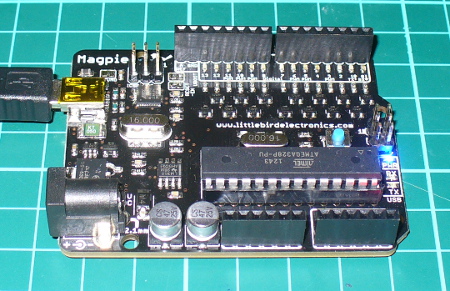
In this article we review the “Magpie” Arduino Uno-compatible board from Little Bird Electronics.

Introduction

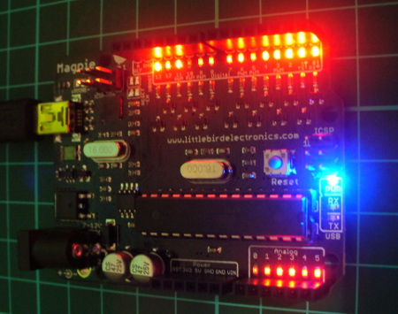
Finally I’m back at the office and have a pile of things to write about. Starting with the subject of this review – the “Magpie” board from Little Bird Electronics in Australia. It seems that a new Arduino-compatible board enters the market every week, thanks to the open-source nature of the platform and the availability of rapid manufacturing. However the Magpie isn’t just any old Arduino Uno knock-off, it has something which helps it stand out from the crowd – status LEDs on every digital and analogue I/O pin. You can see them between the stacking header sockets and the silk-screen labels. For example:

topss

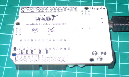
and for the curious, the bottom of the Magpie:

bottomss

At first glance you might think “why’d they bother doing that? I could just wire up some LEDs myself”. True. However having them on the board speeds up the debugging process as you can see when an output is HIGH or LOW – and in the case of an input pin, whether a current is present or not. For the curious the LEDs are each controlled by a 2N7002 MOSFET with the gate connected to the I/O pin, for example:

mosfets

An LED will illuminate as long as the gate voltage is higher than the threshold voltage – no matter the status of the particular I/O pin. And if an I/O pin is left floating it may trigger the LED if the threshold voltage is exceeded at the gate. Therefore when using the Magpie it would be a good idea to set all the pins to LOW that aren’t required for your particular sketch. Even if you remove and reapply power the floating will still be prevalent, and indicated visually – for example:

float

Nevertheless you can sort that out in void setup(), and then the benefits of the LEDs become apparent. Consider the following quick demonstration sketch:

// LBE Magpie board LED demo - John Boxall 18 March 2013
// usual blink delay period
int d=100;
void setup()
{
 // digital pins to outputs
 for (int a=0; a<14; a++)
 {
 pinMode(a, OUTPUT);
 }
 pinMode(A0, OUTPUT);
 pinMode(A1, OUTPUT);
 pinMode(A2, OUTPUT);
 pinMode(A3, OUTPUT);
 pinMode(A4, OUTPUT);
 pinMode(A5, OUTPUT); 
}
void allOn()
// all LEDs on
{
 for (int a=0; a<14; a++)
 {
 digitalWrite(a, HIGH);
 }
 digitalWrite(A0, HIGH);
 digitalWrite(A1, HIGH);
 digitalWrite(A2, HIGH);
 digitalWrite(A3, HIGH);
 digitalWrite(A4, HIGH);
 digitalWrite(A5, HIGH);
}
void allOff()
// all LEDs on
{
 for (int a=0; a<14; a++)
 {
 digitalWrite(a, LOW);
 }
 digitalWrite(A0, LOW);
 digitalWrite(A1, LOW);
 digitalWrite(A2, LOW);
 digitalWrite(A3, LOW);
 digitalWrite(A4, LOW);
 digitalWrite(A5, LOW);
}
void clockWise(int r, int s)
// blinks on and off each LED clockwise
// r - # rotations, s - blink delay 
{
 allOff();
 for (int a=0; a<r; a++)
 {
 for (int b=13; b>=0; --b)
 {
 digitalWrite(b, HIGH);
 delay(s);
 digitalWrite(b, LOW);
 }
 digitalWrite(A5, HIGH);
 delay(s);
 digitalWrite(A5, LOW);
 digitalWrite(A4, HIGH);
 delay(s);
 digitalWrite(A4, LOW);
 digitalWrite(A3, HIGH);
 delay(s);
 digitalWrite(A3, LOW);
 digitalWrite(A2, HIGH);
 delay(s);
 digitalWrite(A2, LOW);
 digitalWrite(A1, HIGH);
 delay(s);
 digitalWrite(A1, LOW);
 digitalWrite(A0, HIGH);
 delay(s);
 digitalWrite(A0, LOW);
 delay(s);
 }
}
void anticlockWise(int r, int s)
// blinks on and off each LED anticlockwise
// r - # rotations, s - blink delay 
{
 allOff();
 for (int a=0; a<r; a++)
 {
 for (int b=0; b<14; b++)
 {
 digitalWrite(b, HIGH);
 delay(s);
 digitalWrite(b, LOW);
 }
 digitalWrite(A0, HIGH);
 delay(s);
 digitalWrite(A0, LOW);
 digitalWrite(A1, HIGH);
 delay(s);
 digitalWrite(A1, LOW);
 digitalWrite(A2, HIGH);
 delay(s);
 digitalWrite(A2, LOW);
 digitalWrite(A3, HIGH);
 delay(s);
 digitalWrite(A3, LOW);
 digitalWrite(A4, HIGH);
 delay(s);
 digitalWrite(A4, LOW);
 digitalWrite(A5, HIGH);
 delay(s);
 digitalWrite(A5, LOW);
 delay(s);
 }
}
void loop()
{
 anticlockWise(3,50);
 clockWise(3,50);
 for (int z=0; z<4; z++)
 {
 allOn();
 delay(100);
 allOff();
 delay(100);
 }
}

… and the results are demonstrated in the following video:

Apart from the LEDs the Magpie offers identical function to that of an Arduino Uno R2 – except the USB microcontroller is an Atmel 16U2 instead of an 8U2, and the USB socket is a mini-USB and not the full-size type.  For the curious you can download the Magpie design files from the product page.

Conclusion

If you’re often experimenting or working with the Arduino’s I/O pins and find yourself wiring up LEDs for testing purposes – the Magpie was made for you. Having those LEDs on the board really does save you if in a hurry to test or check something.

In the meanwhile have fun and keep checking into tronixstuff.com. Why not follow things on twitterGoogle+, subscribe  for email updates or RSS using the links on the right-hand column? And join our friendly Google Group – dedicated to the projects and related items on this website. Sign up – it’s free, helpful to each other –  and we can all learn something.

 The Magpie board used in this article was a promotional consideration supplied by Little Bird Electronics.
The post Review – LBE “Magpie” Arduino-compatible board appeared first on tronixstuff.


  • Newsletter

    Sign up for the PlanetArduino Newsletter, which delivers the most popular articles via e-mail to your inbox every week. Just fill in the information below and submit.

  • Like Us on Facebook