[Evan] found his minion at a McDonald’s and took out essentially everything inside of it, using the minion as a case for all of the interesting bits. First he scavenged a PS/2 port from an old motherboard. An Arduino Nano is wired to an HC-05 Bluetooth chip to translate the signals from the PS/2 peripherals into Bluetooth. The HC-05 chip is a cheaper alternative to most other Bluetooth chips at around $3 vs. $40 for more traditional ones. The programming here is worth mentioning: [Evan] wrote a non-interrupt based and non-blocking PS/2 library for the Arduino that he open sourced which is the real jewel of this project.
Once all the wiring and programming is done [Evan] can turn essentially any old keyboard and mouse into something that’ll work on any modern device. He also put an NFC tag into the minion’s head so that all he has to do to connect the keyboard and mouse is to swipe his tablet or phone past the minion.
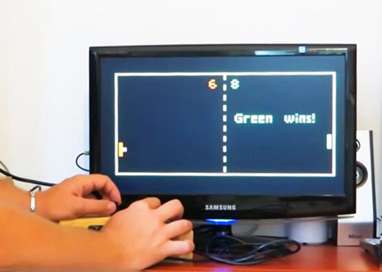
Everyone knows Pong, the first commercially successful arcade video game machine originally release by Atari in 1972. In those years the game helped to establish the video game industry and nowadays is often used by makers to experiment with creating game consoles with Arduino.
Thanks to the VGAx library done by Smaffer, based on the previous work done by Nick Gammon, I have done a little color game for an Arduino Uno working for a VGA monitor. See for details here:
The target was to use an Arduino Uno board without special shields and supporting IC.
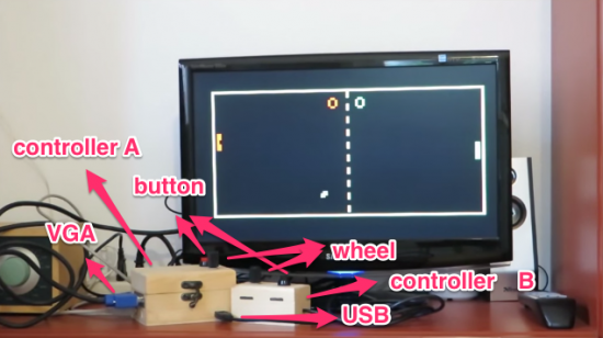
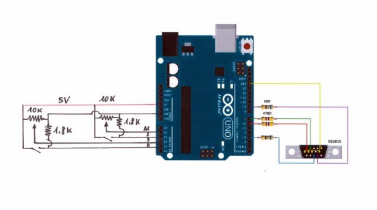
the fundamental components are a button, a potentiometer, few resistors and DSUB15 connector.
Tale a look at the video to see it in action:
Follow the step-by-step guide on Instructables to build one yourself.
Marcelo Jimenez developed a library to use an Arduino as a JTAG programmer. Basically a Python script uploads a XSVF file to an Arduino which interprets it and performs the necessary JTAG manipulation in order to do the programming.
The project is pretty simple because it just uses a few resistors and some wires and the library is included in the Arduino library manager or you can check it on Github.
He also wrote an article to explain some JTAG, SVF and XSVF basics:
I have recently felt the need to incorporate a JTAG port in a project to program a hardware that contained a CPLD. The idea was to both program it and perform some integrity tests on the board. I imagined something using pogo pins, to make it easier and quicker to test everything. I would also write the necessary test routines and generate some kind of report.
With this objective in mind, I have decided to design an Arduino shield to do the job. The testing routines were not really a big deal. And I was sure I would find some JTAG library for Arduino ready to be used. That was not the case.
There were some projects using Arduino to control a JTAG TAP (Test Access Port), but they were all incomplete. And I had no idea what was really JTAG. So I had to study a little bit to make things work for me.
In the end, the challenge proved enlightening. There were some caveats, both from hardware and from software. I’ll try to address them in this article.
If you want to take a photograph with a professional look, proper lighting is going to be critical. [Richard] has been using a commercial lighting solution in his studio. His Lencarta UltraPro 300 studio strobes provide adequate lighting and also have the ability to have various settings adjusted remotely. A single remote can control different lights setting each to its own parameters. [Richard] likes to automate as much as possible in his studio, so he thought that maybe he would be able to reverse engineer the remote control so he can more easily control his lighting.
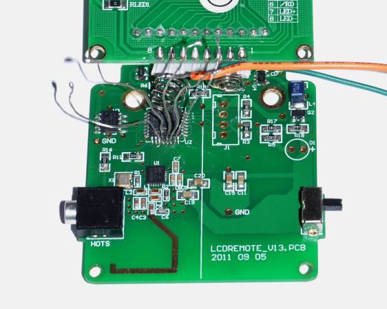
[Richard] started by opening up the remote and taking a look at the radio circuitry. He discovered the circuit uses a nRF24L01+ chip. He had previously picked up a couple of these on eBay, so his first thought was to just promiscuously snoop on the communications over the air. Unfortunately the chips can only listen in on up to six addresses at a time, and with a 40-bit address, this approach may have taken a while.
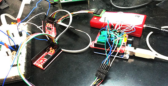
Not one to give up easily, [Richard] chose a new method of attack. First, he knew that the radio chip communicates to a master microcontroller via SPI. Second, he knew that the radio chip had no built-in memory. Therefore, the microcontroller must save the address in its own memory and then send it to the radio chip via the SPI bus. [Richard] figured if he could snoop on the SPI bus, he could find the address of the remote. With that information, he would be able to build another radio circuit to listen in over the air.
Using an Open Logic Sniffer, [Richard] was able to capture some of the SPI communications. Then, using the datasheet as a reference, he was able to isolate the communications that stored information int the radio chip’s address register. This same technique was used to decipher the radio channel. There was a bit more trial and error involved, as [Richard] later discovered that there were a few other important registers. He also discovered that the remote changed the address when actually transmitting data, so he had to update his receiver code to reflect this.
The receiver was built using another nRF24L01+ chip and an Arduino. Once the address and other registers were configured properly, [Richard's] custom radio was able to pick up the radio commands being sent from the lighting remote. All [Richard] had to do at this point was press each button and record the communications data which resulted. The Arduino code for the receiver is available on the project page.
[Richard] took it an extra step and wrote his own library to talk to the flashes. He has made his library available on github for anyone who is interested.
If you want to take a photograph with a professional look, proper lighting is going to be critical. [Richard] has been using a commercial lighting solution in his studio. His Lencarta UltraPro 300 studio strobes provide adequate lighting and also have the ability to have various settings adjusted remotely. A single remote can control different lights setting each to its own parameters. [Richard] likes to automate as much as possible in his studio, so he thought that maybe he would be able to reverse engineer the remote control so he can more easily control his lighting.
[Richard] started by opening up the remote and taking a look at the radio circuitry. He discovered the circuit uses a nRF24L01+ chip. He had previously picked up a couple of these on eBay, so his first thought was to just promiscuously snoop on the communications over the air. Unfortunately the chips can only listen in on up to six addresses at a time, and with a 40-bit address, this approach may have taken a while.
Not one to give up easily, [Richard] chose a new method of attack. First, he knew that the radio chip communicates to a master microcontroller via SPI. Second, he knew that the radio chip had no built-in memory. Therefore, the microcontroller must save the address in its own memory and then send it to the radio chip via the SPI bus. [Richard] figured if he could snoop on the SPI bus, he could find the address of the remote. With that information, he would be able to build another radio circuit to listen in over the air.
Using an Open Logic Sniffer, [Richard] was able to capture some of the SPI communications. Then, using the datasheet as a reference, he was able to isolate the communications that stored information int the radio chip’s address register. This same technique was used to decipher the radio channel. There was a bit more trial and error involved, as [Richard] later discovered that there were a few other important registers. He also discovered that the remote changed the address when actually transmitting data, so he had to update his receiver code to reflect this.
The receiver was built using another nRF24L01+ chip and an Arduino. Once the address and other registers were configured properly, [Richard's] custom radio was able to pick up the radio commands being sent from the lighting remote. All [Richard] had to do at this point was press each button and record the communications data which resulted. The Arduino code for the receiver is available on the project page.
[Richard] took it an extra step and wrote his own library to talk to the flashes. He has made his library available on github for anyone who is interested.
To prevent data corruption when using multiple SPI devices on the same bus, care must be taken to ensure that they are only accessed from within the main loop, or from the interrupt routine, never both. Data corruption can happen when one device is chip selected in the main loop, and then during that transfer an interrupt occurs, chip selecting another device. The original device now gets incorrect data.
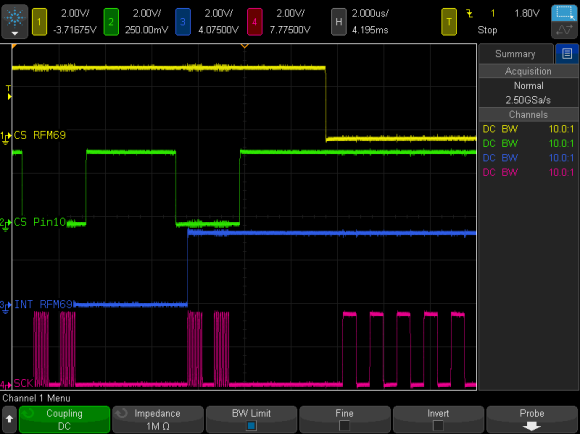
For the last several weeks, [Paul] has been working on a new Arduino SPI library, to solve these types of conflicts. In the above scenario, the new library will generate a blocking SPI transaction, thus allowing the first main loop SPI transfer to complete, before attempting the second transfer. This is illustrated in the picture above, the blue trace rising edge is when the interrupt occurred, during the green trace chip select. The best part, it only affects SPI, your other interrupts will still happen on time. No servo jitter!
This is just one of the new library features, check out the link above for the rest. [Paul] sums it up best: “protects your SPI access from other interrupt-based libraries, and guarantees correct setting while you use the SPI bus”.
I’ve been involved with NOAA Weather Radio for some time and Arduino is a recent passion of mine over the last couple of years. When I found out about the Silicon Labs Si4707 Weather Band IC, it only made sense that I try to use my hardware knowledge and try and come up with a breakout board to make this capability available to the public.
I teamed up with Ray Dees who had done a lot of work with decoding weather radio messages using a different architecture. After a few months of collaboration on software we were able to build a very strong library that enables even the beginner to use all the features of the iC and modify as they see fit for their application. The code is currently optimized for UNO and Mega2560 use.
This code show a basic example of using the color library to make a rainbow appear on RGB LEDs. By varying the hue the rainbow function moves across the whole visible color spectrum.
The purpose of this article is to demonstrate the use of the second (here’s the first) interesting LED display module I discovered on the dealextreme website, for example:
As you can see the display unit holds a total of sixteen seven-segment LED digits using four modules. However thanks to the use of the TM1640 controller IC…
… the entire display is controlled with only four wires – 5V, GND, data in and clock:
Here is the data sheet for the TM1640. The board also ships with the 30cm long four-wire lead and fitted plug. Finally, there is a ‘power on’ LED on the right-hand end of the board:
Getting Started
Now to make things happen. From a hardware perspective – it couldn’t be easier. Connect the 5V and GND leads to … 5V and GND. The data and clock leads will connect to two Arduino digital pins. That’s it. The maximum current drawn by the display with all segments on is ~213mA:
So you should be able to drive this from a normal Arduino-compatible board without any hassle. Please note that the TM1640 IC does heat up somewhat, so you may want to consider some sort of heatsink if intending to max out the display in this manner.
From the software side of things you will need to download and install the TM1638 library (yes) which also handles the TM1640 chip. To simply display text from a string on the display, examine the following sketch:
Which will display:
The sixteen digit binary number in the module.setDisplayToString() line controls the decimal points – 0 for off and 1 for on. For example, changing it to
will display:
You can also display text in a somewhat readable form – using the characters available in this list. Displaying numbers is very easy, you can address each digit individually using:
where x is the digit, y is the position (0~15), and true/false is the decimal point. At this time you can’t just send a long integer down to the display, so you will need to either convert your numbers to a string or failing that, split it up into digits and display them one at a time.
In the following example sketch we display integers and unsigned integers by using the C command sprintf(). Note the use of %i to include an integer, and %u for unsigned integer:
And the resulting output:
Now you have an idea of what is possible, a variety of display options should spring to mind. For example:
Again, this display board was a random, successful find. When ordering from dealextreme, do so knowing that your order may take several weeks to arrive as they are not the fastest of online retailers; and your order may be coming from mainland China which can slow things down somewhat. Otherwise the module worked well and considering the minimal I/O and code requirements, is a very good deal.
Have fun and keep checking into tronixstuff.com. Why not follow things on twitter, Google+, subscribe for email updates or RSS using the links on the right-hand column, or join our Google Group – dedicated to the projects and related items on this website. Sign up – it’s free, helpful to each other – and we can all learn something.
Planet Arduino is, or at the moment is wishing to become, an aggregation of public weblogs from around the world written by people who develop, play, think on Arduino platform and his son. The opinions expressed in those weblogs and hence this aggregation are those of the original authors. Entries on this page are owned by their authors. We do not edit, endorse or vouch for the contents of individual posts. For more information about Arduino please visit www.arduino.cc
You are currently browsing the archives for the Library category.