Posts | Comments

Planet Arduino

Archive for the ‘radio’ Category

Oct
13

Arduino WebRadio player

arduino, ENC28J60, ethernet, LCD, mp3, Nokia 5110 LCD, player, radio, VS1053B, webradio Comments Off on Arduino WebRadio player 

webradio_pic2

Arduino WebRadio player is an inexpensive WebRadio player that can plays internet audio streams up to 64-kbps and is based on mp3, aac and wma audio formats.

The main components are:

  • Arduino Pro mini board
  • ENC28J60 ethernet module
  • VS1053B mp3, aac, wma decoder
  • 84×48 dot matrix LCD module (Nokia 5110)

Arduino WebRadio player - [Link]

Strobe Remote

If you want to take a photograph with a professional look, proper lighting is going to be critical. [Richard] has been using a commercial lighting solution in his studio. His Lencarta UltraPro 300 studio strobes provide adequate lighting and also have the ability to have various settings adjusted remotely. A single remote can control different lights setting each to its own parameters. [Richard] likes to automate as much as possible in his studio, so he thought that maybe he would be able to reverse engineer the remote control so he can more easily control his lighting.

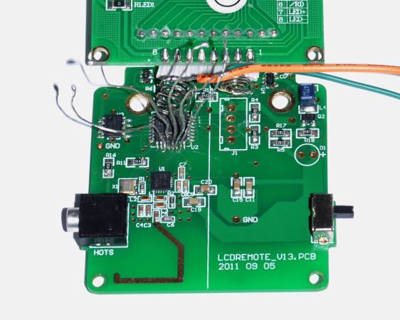
[Richard] started by opening up the remote and taking a look at the radio circuitry. He discovered the circuit uses a nRF24L01+ chip. He had previously picked up a couple of these on eBay, so his first thought was to just promiscuously snoop on the communications over the air. Unfortunately the chips can only listen in on up to six addresses at a time, and with a 40-bit address, this approach may have taken a while.

Not one to give up easily, [Richard] chose a new method of attack. First, he knew that the radio chip communicates to a master microcontroller via SPI. Second, he knew that the radio chip had no built-in memory. Therefore, the microcontroller must save the address in its own memory and then send it to the radio chip via the SPI bus. [Richard] figured if he could snoop on the SPI bus, he could find the address of the remote. With that information, he would be able to build another radio circuit to listen in over the air.

Using an Open Logic Sniffer, [Richard] was able to capture some of the SPI communications. Then, using the datasheet as a reference, he was able to isolate the communications that stored information int the radio chip’s address register. This same technique was used to decipher the radio channel. There was a bit more trial and error involved, as [Richard] later discovered that there were a few other important registers. He also discovered that the remote changed the address when actually transmitting data, so he had to update his receiver code to reflect this.

The receiver was built using another nRF24L01+ chip and an Arduino. Once the address and other registers were configured properly, [Richard's] custom radio was able to pick up the radio commands being sent from the lighting remote. All [Richard] had to do at this point was press each button and record the communications data which resulted. The Arduino code for the receiver is available on the project page.

[Richard] took it an extra step and wrote his own library to talk to the flashes. He has made his library available on github for anyone who is interested.


Filed under: Arduino Hacks, radio hacks

mote

One of the apparent unofficial themes of The Hackaday Prize is the Internet of Things and home automation. While there were plenty of projects that looked at new and interesting ways to turn on a light switch from the Internet, very few took a good, hard look at the hardware required to do that. [Felix]‘s Moteino is one of those projects.

The Moteino is based on the Arduino, and adds a low-cost radio module to talk to the rest of the world. The module is the HopeRF RFM12B or RFM69. Both of these radios operate in the ISM band at 434, 868, or 915 MHz. Being pretty much the same as an Arduino with a radio module strapped to the back, programming is easy and it should be able to do anything that has been done with an ATMega328.

[Felix] has been offering the Moteino for a while now, and already there are a few great projects using this platform. In fact, a few other Hackaday Prize entries incorporated a Moteino into their design; Plant Friends used it in a sensor node, and this project is using it for texting and remote control with a cell phone.


SpaceWrencherThe project featured in this post is a semifinalist in The Hackaday Prize.


Filed under: Arduino Hacks, radio hacks, The Hackaday Prize
Jun
27

Generate Clocks with the SI5351 and an Arduino

arduino, arduino hacks, clock, PLL, radio, radio hacks, SI5351 Comments Off on Generate Clocks with the SI5351 and an Arduino 

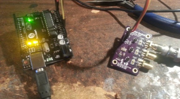
A SI5351 clock generator chip and an Arduino

If you’re dealing with RF, you’ll probably have the need to generate a variety of clock signals. Fortunately, [Jason] has applied his knowledge to build a SI5351 library for the Arduino and a breakout board for the chip.

The SI5351 is a programmable clock generator. It can output up to eight unique frequencies at 8 kHz to 133 MHz. This makes it a handy tool for building up RF projects. [Jason]‘s breakout board provides 3 isolated clock outputs on SMA connectors. A header connects to an Arduino, which provides power and control over I2C.

If you’re looking for an application, [Jason]‘s prototype single-sideband radio shows the chip in action. This radio uses two of the SI5351 clocks: one for the VFO and one for the BFO. This reduces the part count, and could make this design quite cheap.

The Arduino library is available on Github, and you can order a SI5351 breakout board from OSHPark.


Filed under: Arduino Hacks, radio hacks
Jan
24

Decoding Weather Radio messages with Arduino

arduino, Library, radio, weather Comments Off on Decoding Weather Radio messages with Arduino 

WeatherRadio

Arduino user Vogel1230 wrote us:

I’ve been involved with NOAA Weather Radio for some time and Arduino is a recent passion of mine over the last couple of years. When I found out about the Silicon Labs Si4707 Weather Band IC, it only made sense that I try to use my hardware knowledge and try and come up with a breakout board to make this capability available to the public.

I teamed up with Ray Dees who had done a lot of work with decoding weather radio messages using a different architecture. After a few months of collaboration on software we were able to build a very strong library that enables even the beginner to use all the features of the iC and modify as they see fit for their application. The code is currently optimized for UNO and Mega2560 use.


Nov
07

RadioduinoWRT – a do it yourself webradio

arduino, audio, radio, webradio, WR703N Comments Off on RadioduinoWRT – a do it yourself webradio 

WK1600_DSC_0005_video

Raffael @ code-bude.net build a webradio by himself. It’s made from an Arduino, an hacked TP-Link WR703N router and some interface parts.

Today I want to present you one of my larger craft projects. This time it is not just about software, but also about the associated hardware. What is it? A web radio!

I like to listen to internet radio stations, but I didn’t want to run my pc only for listening to webradios. Connecting my phone to my stereo either wasn’t a solution, since I’d rather wear this with me, because I don’t want to run for each SMS / Whatsapp message to the music system. And because I always like to tinker, it was obvious to build a web radio as a standalone device myself.

RadioduinoWRT – a do it yourself webradio - [Link]

Jun
17

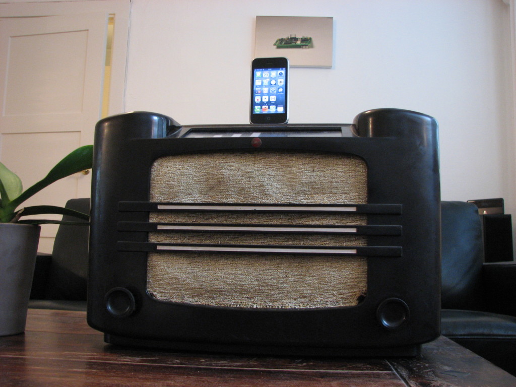
Vintage radio hacked into a docking station

arduino, duemilanove, Hacks, radio, tutorial Comments Off on Vintage radio hacked into a docking station 

Vintage radio hacked into a docking station

Mr. Oyvind from Oslo sent us a cool  hack of a 75-years-old radio into an iPhone dock using an Arduino.

On his website you can read the complete tutorial or download the code and below you can have more details on the way he used the board:

the Arduino is used to read the state of the dual potentiometer that controls the volume and then translate this value into a certain number of LEDs being lit on the volume indicator.
I am using a Duemilanove. The code for the project is very simple and can be found here:http://www.build-electronic-circuits.com/wp-content/uploads/2013/05/radio_ino.zip
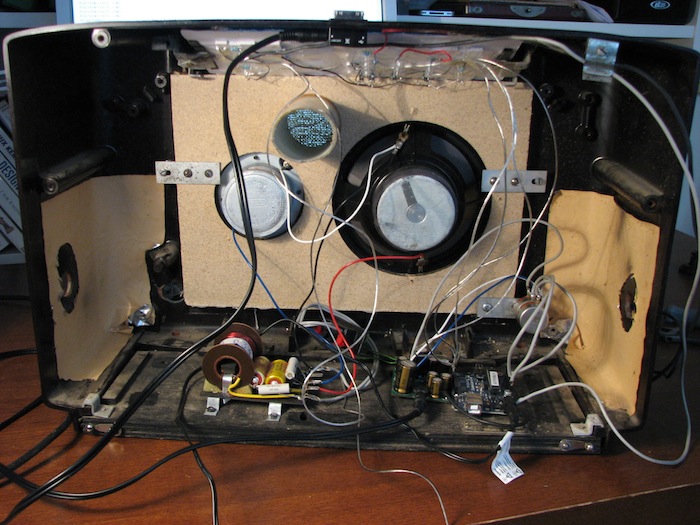
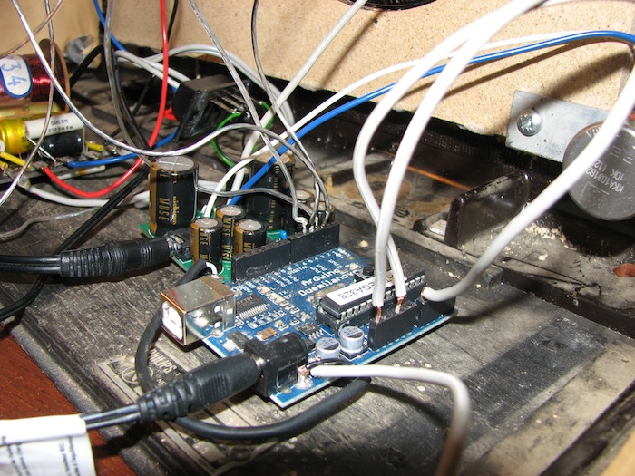
  •  An overview of the inside of the dock (very messy, I know ;) )
dock overview
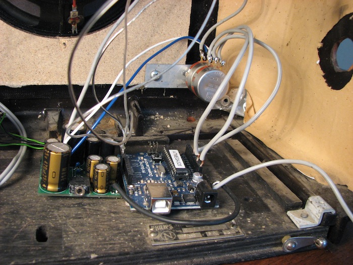
  •  I am using a dual potentiometer (2 pots in one). Here you can see one pot connected to the amplifier on the left to control the volume, and the other connected to the Arduino on the right to read the position of the pot.

dock pot amp arduino

  • Here you can see the 4 wires used to control the volume display connected to digital input 2, 3, 4 and 5 on the left side of the board. And you can see the potentiometer connected to 3.3V, analog input 0 and ground on the right side of the board.

dock connections


  • Newsletter

    Sign up for the PlanetArduino Newsletter, which delivers the most popular articles via e-mail to your inbox every week. Just fill in the information below and submit.

  • Like Us on Facebook