Hearing loss is a common problem for many – especially those who may have attended too many loud concerts in their youth. [mircemk] had recently been for a hearing test, and noticed that the procedure was actually quite straightforward. Armed with this knowledge, he decided to build his own test system and document it for others to use.
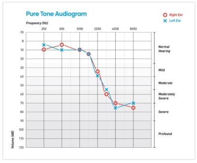
Resultant audiogram from the device showing each ear in a different color
By using an Arduino to produce tones of various stepped frequencies, and gradually increasing the volume until the test subject can detect the tone, it is possible to plot an audiogram of hearing threshold sensitivity. Testing each ear individually allows a comparison between one side and the other.
[mircemk] has built a nice miniature cabinet that holds an 8×8 matrix of WS2812 addressable RGB LEDs. A 128×64 pixel OLED display provides user instructions, and a rotary encoder with push-button serves as the user input.
Of course, this is not a calibrated professional piece of test equipment, and a lot will depend on the quality of the earpiece used. However, as a way to check for gross hearing issues, and as an interesting experiment, it holds a lot of promise.
There is even an extension, including a Class D audio amplifier, that allows the use of bone-conduction earpieces to help narrow down the cause of hearing loss further.
You probably don’t want to lose a leg, but if you have to there are many options now that were unthinkable not long ago. That is, if you can afford them. A microprocessor knee — a prosthetic with some smarts in it — can run anywhere from $25,000 to well over $100,000. However [Lucas Galey], a PhD candidate at the University of Texas El Paso in a recent paper claims to be able to produce a comparable artificial knee for under $1,000. If the paper is too long to read, Amplitude has a good summary including what it means to people who need them.
Of course, the cost of making something like this is almost incidental. The cost of approvals, testing, and other factors mean that even with about $500 in parts, the retail price would be much higher. Probably not $25,000, though.
In the device is an Arduino and some sensors that monitor the user’s gait among other things. Apparently [Lucas] volunteers with an organization called LIMBS International that provides prosthetics to people in developing nations. His design in an outgrowth of a low-cost passive knee developed by the organization. That knee, however, doesn’t meet Federal standards, so you can’t get one in the United States.
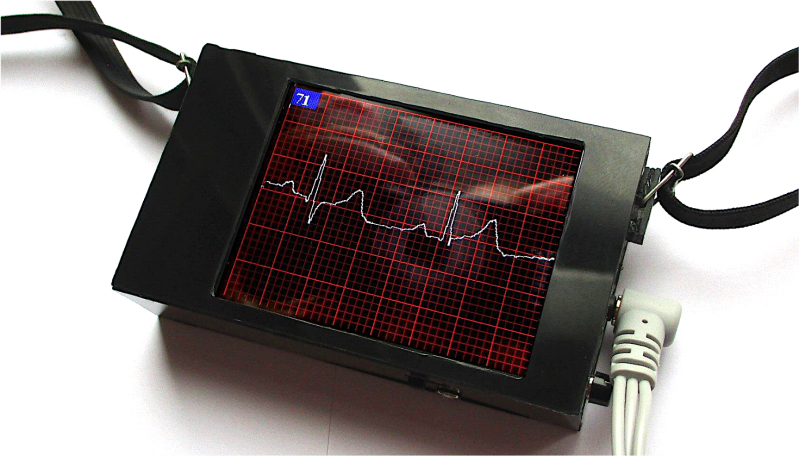
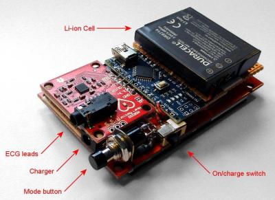
If you’ve followed Hackaday for any period of time, you’re probably already somewhat familiar with the hardware needed to record the ECG. First, you need a high input impedance instrumentation amplifier to pick up the millivolt signal from electrical leads carefully placed on the willing subject’s body. To accomplish this, he used an AD8232 single-lead ECG module (we’ve actually seen this part used to make a soundcard-based ECG). This chip has a built-in instrumentation amplifier as well as an optional secondary amplifier for additional gain and low-pass filtering. The ECG signal is riddled with noise from mains that can be partially attenuated with a simple low-pass filter. Then, [Peter] uses an Arduino Nano to sample the output of the AD8232, implement a digital notch filter for added mains noise reduction, and display the output on a 2.8″ TFT display.
Other than the circuit itself, two things about his project really caught our attention. [Peter] walks the reader through all the different safety considerations for a commercial ECG device and applies these principles to his simple DIY setup to ensure his own safety. As [Peter] put it, professional medical electronics should follow IEC 60601. It’s a pretty bulky document, but the main tenets quoted from [Peter’s] write-up are:
limiting how much current can pass through the patient
how much current can I pass through the patient?
what electrical isolation is required?
what happens if a “component” fails?
how much electromagnetic interference can I produce?
what about a defibrillator?
[Peter] mentions that his circuit itself does not fully conform to the standard (though he makes some honest attempts), but lays out a crude plan for doing so. These include using high-valued input resistors for the connections to the electrodes and also adding a few protection diodes to the electrode inputs so that the device can withstand a defibrillator. And of course, two simple strategies you always want to follow are using battery power and placing the device in a properly shielded enclosure.
[Peter] also does a great job breaking down the electrophysiology of the heart and relates it to terms maybe a bit more familiar to non-medical professionals. Understanding the human heart might be a little less intimidating if we relate the heart to a simple voltage source like a battery or maybe even a function generator. You can imagine the ions in our cells as charger carriers that generate electrical potential energy and nerve fibers as electrical wires along which electrical pulses travel through the body.
Honestly, [Peter] has a wealth of information and tools presented in his project that are sure to help you in your next build. You might also find his ECG simulator code really handy and his low-memory display driver code helpful as well. Cool project, [Peter]!
Some of us are oblivious to how often we touch our faces. The current finding is we reach for our eyes, nose, or mouth every three to four minutes. Twenty times per hour is an awful lot of poking, picking, itching, and prodding when we’re supposed to keep our hands away from glands that can transmit and receive disease. To curb this habit and enter the 2020 Hackaday Prize, [Lloyd lobo] built a proof-of-concept device that sounds the alarm when you reach for your face.
We see an Arduino Uno connected to the classic HC-SR04 ultrasonic distance sensor, an LED, and we have to assume a USB battery pack. [Lloyd] recommends the smaller Nano, we might reach for the postage-stamp models and swap the ultrasonic module out for the much smaller laser time of flight sensor. At its soul, this is an intruder alarm. Instead of keeping siblings out of your room, you will be keeping your hands out of the area below the bill of the hat where the sensor is mounted. If you regularly lift a coffee cup to your lips, it might chastise you, and if you chew sunflower seeds, you might establish a tempo. *crunch* *chip* *beep* *crunch* *chip* *beep*
In many parts of the world the COVID-19 pandemic is causing shortages in hospital space, staff, medical supplies, and equipment. Severe cases may require breathing support, but there are only so many ventilators available. With that in mind, MIT is working on FDA approval of an emergency ventilator system (E-Vent). They have submitted the design to the FDA for fast track review. The project is open source, so once they have approval the team will release all the data needed to replicate it.
The design is actually made simple by using something that is very common: a manual resuscitator. You have doubtlessly seen these on your favorite medical show. It is the bag someone squeezes while the main character struggles valiantly to save their patient. Of course, having someone sit and squeeze the bag for days on end for thousands of people isn’t very practical and that’s where they’ve included an Arduino-controlled motor to automate the process.
The tricky thing is that, forcing air into your lungs isn’t always good for them. Even healthy lungs can be stressed by too much inflation and people who already have lung problems may be able to handle only a tenth of what a healthy set can manage. That’s why the device needs a closed loop control system that monitors pressure from the patient and modifies the flow.
Any solution should be utilized only in a healthcare setting with direct monitoring by a clinical professional. While it cannot replace an FDA-approved ICU ventilator, in terms of functionality, flexibility, and clinical efficacy, the MIT E-Vent is anticipated to have utility in helping free up existing supply or in life-or-death situations when there is no other option.
Further, any low-cost ventilator system must take great care regarding providing clinicians with the ability to closely control and monitor tidal volume, inspiratory pressure, bpm, and I/E ratio, and be able to provide additional support in the form of PEEP, PIP monitoring, filtration, and adaptation to individual patient parameters. We recognize, and would like to highlight for anyone seeking to manufacture a low-cost emergency ventilator, that failing to properly consider these factors can result in serious long-term injury or death.
This isn’t a unique idea, and the MIT team provides links to other similar projects. The team’s work is not totally online yet, because they are still testing. For example, the acrylic apparatus that squeezes the bag may not hold up to the repetitive stress very well. The team may look to other projects that predated the crisis. For example, have a look at the AIR device presented at a conference last year in the video below. There’s also this interesting document from a Johns Hopkins resident.
Almost as interesting as the device itself is the comments people are leaving about the design. It is a great example of how the Internet opens up totally new ways to collaborate on a critical problem like this one.
The various displays and interfaces in Star Trek, especially The Original Series, were intentionally designed to be obtuse and overly complex so they would appear futuristic to the audience. If you can figure out how Sulu was able to fly the Enterprise with an array of unlabeled buttons and rocker switches, we’d love to hear it. But one area of the ship where this abstract design aesthetic was backed off a bit was sickbay, as presumably they wanted the audience to be able to understand at a glance whether or not Kirk or Spock were going to pull through their latest brush with death (spoilers: they’re fine).
For his latest project, [XTronical] has recreated the classic displays from Dr McCoy’s sickbay with an Arduino Nano and a 2.8 inch LCD display. It even has a speaker and MP3 player module to recreate the “heartbeat” sound from the original show. The whole thing looks and sounds phenomenal, and would be a perfect desk toy for the classic Trek aficionado. But this isn’t just a toy, it’s a fully functional medical scanner.
Of course, this little gadget can’t tell you if you’ve come down with a nasty case of Rigellian fever, but it can read your vitals using a MAX30100 pulse oximeter module and DS18B20 thermometer. In fact, it actually has two DS18B20 sensors: one to measure ambient temperature, the other to measure skin temperature. With those two figures, [XTronical] says it can calculate your core body temperature. The only thing that’s made up is the blinking “Respiration” indicator, that one’s just an estimate.
Students at the University of Illinois at Urbana-Champaign have a brain-computer interface that can measure brainwaves. What did they do with it? They gave it to Alma, a golden labrador, as you can see in the video below. The code and enough info to duplicate the electronics are on GitHub.
Of course, the dog doesn’t directly generate speech. Instead, the circuit watches her brainwaves via an Arduino and feeds the raw data to a Raspberry Pi. A machine learning algorithm determines Alma’s brainwave state and plays prerecorded audio expressing Alma’s thoughts.
Alma’s collar duplicates — to some degree — the fictional collar from the movie Up. Of course, Dug was a bit more loquacious. It isn’t very clear from the video how many states the program classifies. A quick peek at the code reveals five audio clips but only one appears to be wired to the recognizer — the one for a treat. We think it might be a harder problem to figure out when the dog does not want a treat.
The last time we saw a talking dog collar it was phone-controlled. If you really want to probe a brain — canine or human — you could do worse than to check out OpenHardwareExG.
Building a real-life version of the Star Trek tricorder has been the goal of engineers and hackers alike since the first time Dr McCoy complained about being asked to work outside of his job description. But while modern technology has delivered gadgets remarkably similar in function, we’ve still got a long way to go before we replicate 24th century Starfleet design aesthetic. Luckily there’s a whole world of dedicated hackers out there who are willing to take on the challenge.
[Taste The Code] is one such hacker. He wanted to build himself a practical gadget that looked like it would be at home on Picard’s Enterprise, so he gathered up the components to build a hand-held heart rate monitor and went in search for a suitable enclosure. The electronics were simple enough to put together thanks to the high availability and modularity we enjoy in a post-Arduino world, but as you might expect it’s somewhat more difficult to put it into a package that looks suitably sci-fi while remaining functional.
Internally his heart rate monitor is using an Arduino Pro Mini, a small OLED screen, and a turn-key pulse sensor which was originally conceived as a Kickstarter in 2011 by “World Famous Electronics”. Wiring is very simple: the display is connected to the Arduino via I2C, and the pulse sensor hooks up to a free analog pin. Everything is powered by 3 AA batteries delivering 4.5 V, so he didn’t even need a voltage regulator or the extra components required for a rechargeable battery pack.
Once everything was confirmed working on a breadboard, [Taste The Code] started the process of converting a handheld gyroscopic toy into the new home of his heart rate monitor. He kept the battery compartment in the bottom, but everything else was stripped out to make room. One hole was made on the pistol grip case so that a finger tip could rest on the pulse sensor, and another made on the side for the OLED screen. This lets the user hold the device in a natural way while getting a reading. He mentions the sensor can be a bid fiddly, but overall it gives accurate enough readings for his purposes.
Inspired by an old Old Spice commercial, [Juliodb96] decided he too wanted to make music by flexing his muscles. An Arduino and a MyoWare sensor did the trick. However, he also tells you how to make your own sensors, if you are so inclined. You can see the instrument in action in the video below.
If you use the ready-made MyoWare sensors, this is a pretty easy project. You just respond to sensor input by playing some notes. If you decide to roll your own, you’ll have some circuit building ahead of you.
In particular, the signal conditioning for the sensors involves filtering to eliminate signals not in the 20 Hz to 300 Hz passband, several amplifiers, a rectifier, and a clipper. This requires 3 IC packages and a handful of discrete components.
Unlike the original commercial (see the second video, below), there are no moving parts for actuating actual instruments. However, that wouldn’t be hard to add with some servo motors, air pumps, and the like. This may seem frivolous, but we had to wonder if it could be used to allow musical expression for people who could not otherwise play an instrument.
This isn’t the first time we’ve seen the MyoWare in action. We’ve even talked about signal processing that is useful for this kind of application.
Planet Arduino is, or at the moment is wishing to become, an aggregation of public weblogs from around the world written by people who develop, play, think on Arduino platform and his son. The opinions expressed in those weblogs and hence this aggregation are those of the original authors. Entries on this page are owned by their authors. We do not edit, endorse or vouch for the contents of individual posts. For more information about Arduino please visit www.arduino.cc
You are currently browsing the archives for the Medical hacks category.