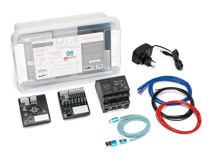
Arduino PLC Starter Kit combines the Arduino Opta micro PLC, the Arduino DIN Simul8 digital input simulator and power distribution board, and the Arduino DIN Celsius board with two independent heater circuits and one temperature sensor acting as a temperature laboratory. The kit is supported by the Arduino PLC IDE first introduced in 2022 and comes with various cables and a power supply that allows users to quickly get started. Arduino says the kit targets the education of students aged 17 years and more. It includes 20 hours of lessons going through the history of programmable logic controllers, Modbus RS-485 communications, and how PLCs integrate with industrial simulated systems. The main hardware and software components of the kits are: Arduino Opta WiFi micro PLC based on an STMicro STM32H747XI dual-core Arm Cortex-M7/M4 MCU, offering Ethernet and RS485 communication interfaces, and exposing eight digital/analog inputs, plus four relay outputs. DIN Rail-mountable [...]
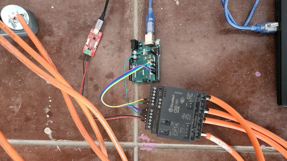
We all know that one neighbor who always goes the extra mile when decorating for the holidays, and after taking inspiration from these large displays of light and sound, Marcelo Arredondo, Andres Sabas, and Andrea ZGuz of the Electronic Cats crew decided to build a smaller version for their Christmas tree using the Arduino Opta micro PLC.
The team chose to create their music-synchronized light show with the Opta because of its reliability and bank of four built-in relays that could be utilized to switch specific light strings on or off. Lining up and triggering certain lighting effects for the music was all handled through the open-source Vixen Lights software. In here, the Opta was configured as a quad-channel controller that receives its commands over a GPIO connection sent by an Arduino UNO mediator. The PLC is programmed visually to read a programmable input pin for each relay and then leverage a comparator to toggle the relay when the signal is high.
Back in the Vixen Light software, the team imported their favorite Christmas song and began the process of charting it. First, they generated markers over the audio waveform to signify the beats and overall tempo. Next, various effects were added to the timeline which trigger the lighting channels in a particular sequence. Lastly, the UNO was flashed with a sketch that allowed it to read the incoming Serial data from Vixen over USB and then toggle its digital outputs for the Opta to register.
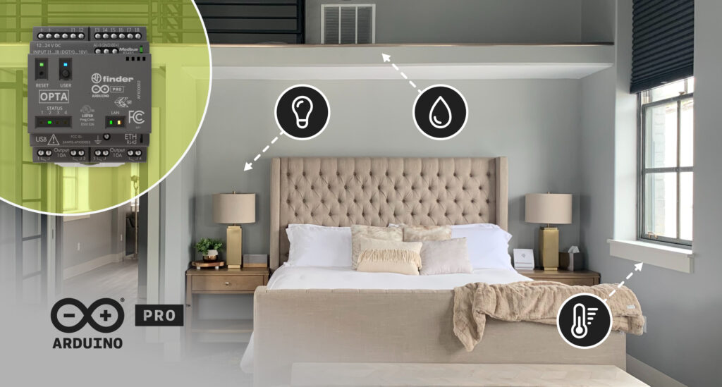
Hospitality professionals are constantly looking for ways to offer guests an enhanced experience while improving operational efficiency and optimizing energy management. To achieve this, they require cost-effective solutions that are easy to install and maintain while also providing the scalability of future-ready systems – such as automating hotel rooms or B&B rentals to increase safety, comfort, and energy savings.
Indeed, automation can be integrated seamlessly in various aspects including climate control, lighting, security, and entertainment. Upgrading these functions allows guests to enjoy customization and convenience throughout their stay, and staff to efficiently manage room settings remotely. Moreover, hoteliers can achieve substantial energy savings through optimized control and scheduling, contributing to sustainability goals.
Long-term scalability and future-proofing of automation systems, however, can be an issue. As hotels and rental properties undergo renovations or expansions, the ideal solution should accommodate changes without requiring substantial modifications or replacements. Adopting open and standardized protocols, as well as selecting flexible and modular automation projects, can help mitigate these challenges and provide a foundation for future enhancements.
Our solution
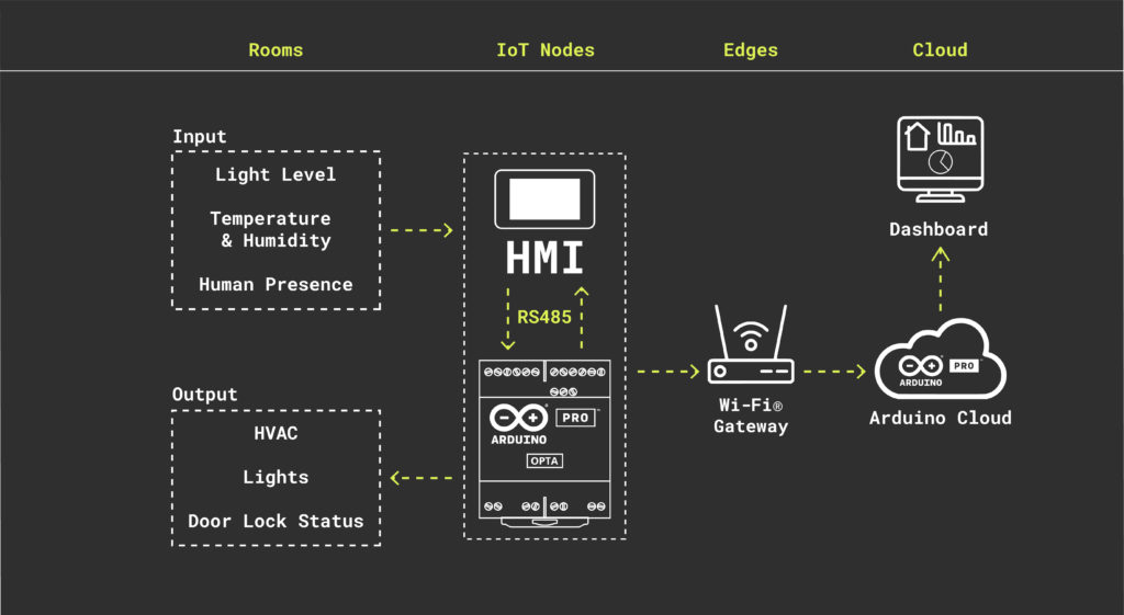
A comprehensive IoT automation solution can address these challenges effectively by aggregating sensor and user data and then intelligently managing lighting, cooling/heating and more – for a smart, connected experience. The elements required to achieve this kind of outcome are environmental sensors, a programmable logic controller (PLC), a human-machine interface (HMI), and cloud connectivity.
Programmable logic controller (PLC)
PLC-based automation systems are widely used due to their reliability, flexibility, and ability to handle complex tasks. Arduino Pro’s Opta microPLC can serve as the central control unit for hotel room automation by connecting and monitoring various devices and subsystems such as HVAC (heating, ventilation, and air conditioning), lighting and door locks. The microPLC receives data from sensors and users and processes them to trigger appropriate actions or adjustments in the room.
Human-machine interface (HMI)
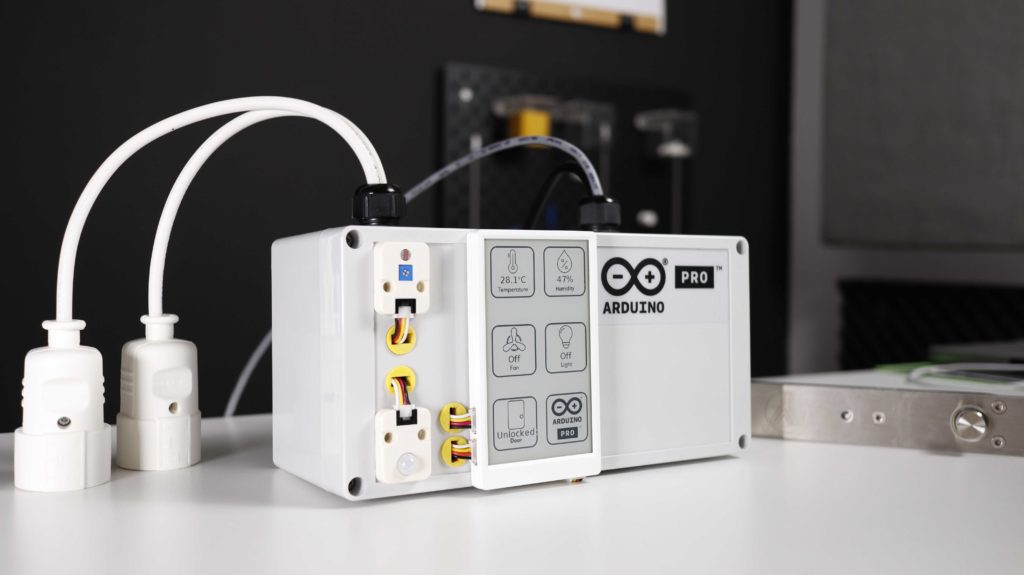
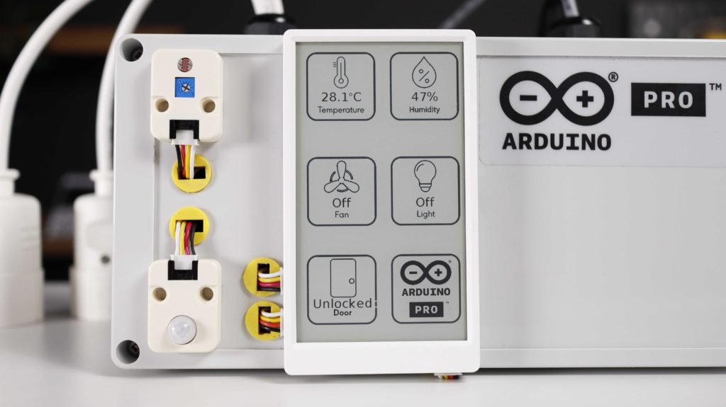
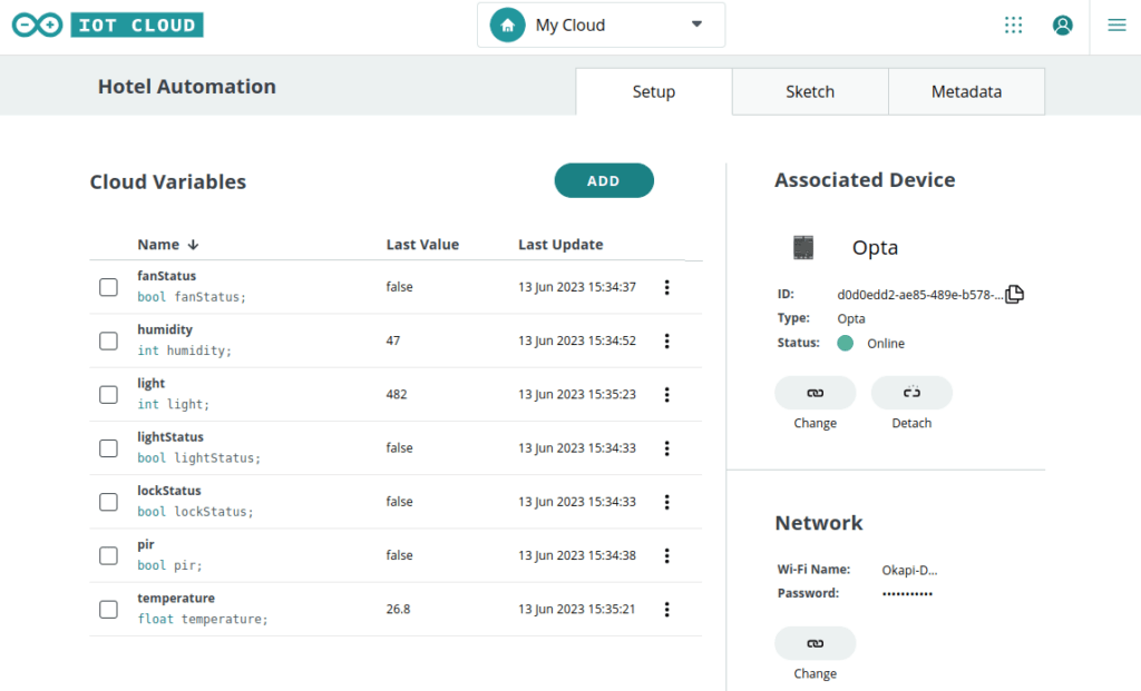
A touchscreen panel through which guests and staff can control various room parameters – such as lighting status, fan status, and door lock status – provides a user-friendly and intuitive interface to interact with the automation system. This HMI also communicates data to the microPLC for execution.
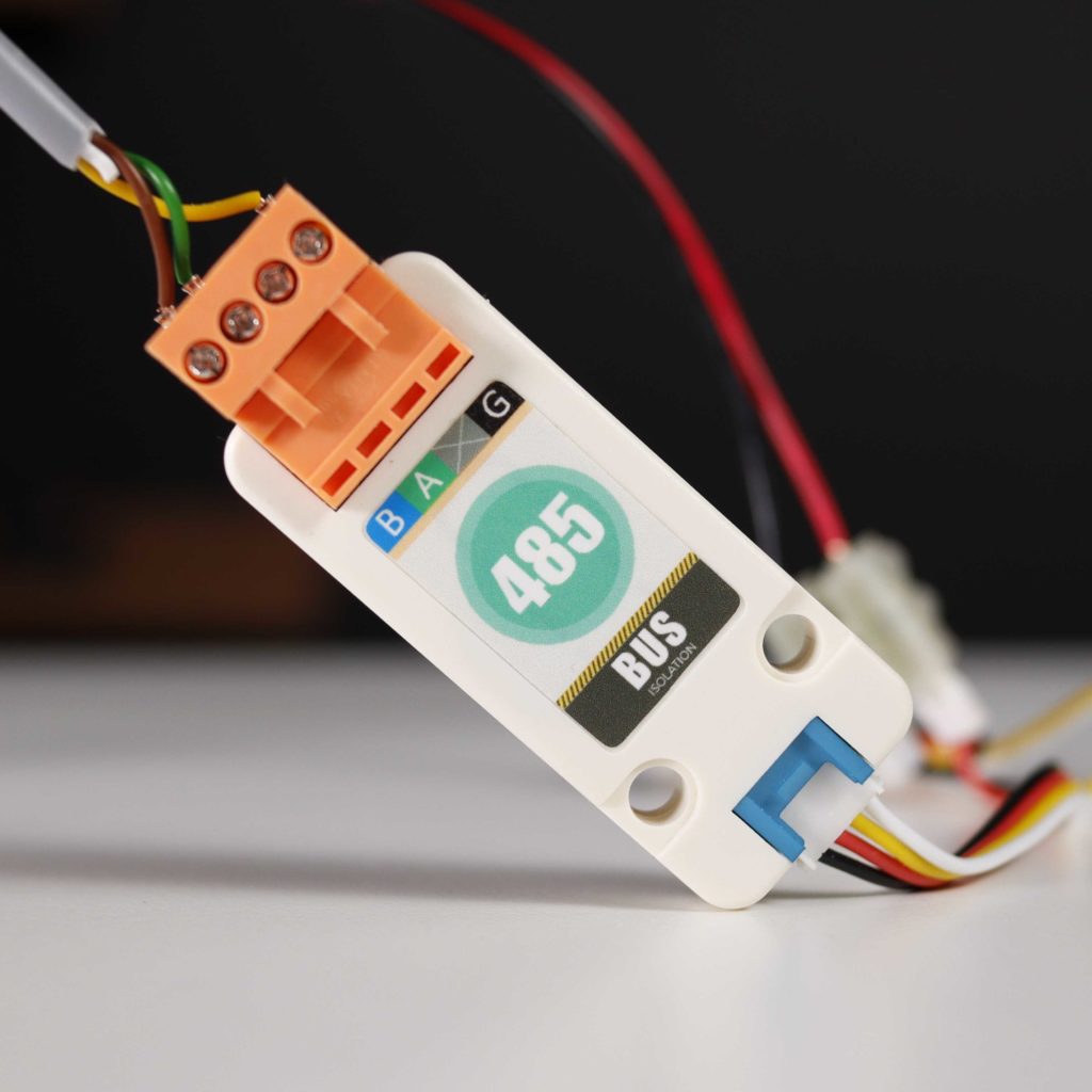
The Modbus communication protocol
The HMI and Opta PLC communicate via Modbus RTU over RS-485. Modbus RTU communication protocol is widely adopted in industrial applications due to its reliability, provided by the physical layer strength and by the cyclic redundancy check included in the data packets. It allows for multiple devices to be connected to the same bus, forming a multidrop network where each device has a unique address, used to identify the recipient of the transmitted data. The Arduino Opta can communicate with other Modbus devices, such as sensors, actuators, or traditional PLCs, by addressing them individually.
IoT Cloud solution
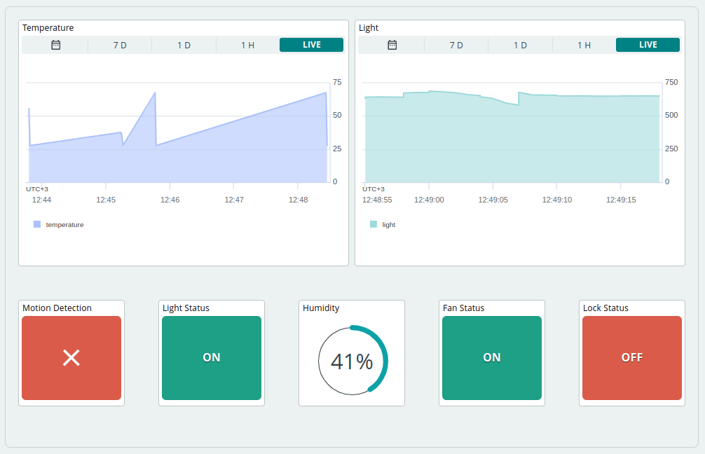
Cloud connectivity enables seamless communication between the hotel room or rental property’s automation system and the central management system. The Opta and HMI connect to the cloud infrastructure, allowing remote access, monitoring, and control of multiple locations. The solution also enables data logging and analytics for better energy management, predictive maintenance, and guest experience personalization.
Solving it with Arduino Pro
Let’s get into the details of how this solution can be put into action, and identify the hardware and software resources needed for deployment. Arduino Opta is a great option for deploying building automation solutions, as it offers simple integration with current systems, real-time control capabilities, support for Over-The-Air (OTA) firmware updates, and Hardware-To-Cloud data security. The Arduino Pro ecosystem allows users to benefit from easy integration, along with a range of scalable, secure, and professionally supported services.
The Arduino IDE 2.0 can be used to program Opta using C/C++. Opta acts as the main controller, communicating with the HMI via the Modbus RTU protocol. The HMI gathers data from various sensors – including light, temperature and humidity, and PIR (movement sensor) – as well as user inputs from its interface buttons related to room climate, lights, and door lock status. It then forwards this data to Opta, which controls the relay outputs that will activate the lights, thermostat or door lock.
Opta also sends this data via Wi-Fi® to the Arduino IoT Cloud. After connecting it to the Arduino Cloud using the Arduino Create Agent, cloud variables corresponding to the sensor data being monitored can be defined.
Arduino Pro’s Opta microPLC offers an ideal solution for the automation of hotel rooms and B&Bs or rental properties. By leveraging standard communication protocols, easy integration, real-time control capabilities, secure hardware-to-cloud data exchange and remote access to multiple rooms from a centralized location, Opta provides the cornerstone of a comprehensive platform for smart hospitality.
On the surface, a programmable logic controller (PLC) might seem like nothing more than a generic microcontroller, perhaps outfitted to operate in industrial settings with things like high temperatures or harsh vibrations. While this is true to some extent, PLCs also have an international standard for their architecture and programming languages. This standard is maintained by the International Electrotechnical Commission, making it so that any device built under these specifications will be recognizable to control engineers and maintenance personnel worldwide. And, if you use this standard when working with certain Arduinos, this common platform can become a standard-compliant PLC as well.
The IDE itself supports programming ladder diagrams, functional block diagrams, and other programming systems covered under the IEC 61131-3 standard. Not only that, it allows the combination of these types of PLC programming with Arduino sketches. The system offers many of the perks of PLC programming alongside the familiar Arduino platform, and supports a number of protocols as well including CANOpen, Modbus RTU, and Modbus TCP. It can also be used for monitoring a PLC system, essentially adding IoT capabilities to existing systems, enabling continuous monitoring, debugging, and program updates.
While not every Arduino is a great platform to build a PLC around, there are a few available for those looking for a system a little less proprietary and a little more user-friendly than typical PLC systems tend to be. There’s a reason that PLCs are built around an international standard and generally have certain hardware in mind to run it, though, and this comparison of a Raspberry Pi with an off-the-shelf PLC goes into detail about why certain components aren’t good choices for PLCs.
We’re all used to general purpose microcontroller boards such as the Arduino or its many imitators, but perhaps we don’t see as much of their industrial cousins. A programmable logic controller (PLC) is a computer designed to automate industrial machinery, and comes with protected interfaces and usually a specific PLC programming environment. Thus [Galopago]’s work with an inexpensive Chinese PLC clone is especially interesting, providing a route forward to using it within the Arduino IDE ecosystem.
Opening it up, the processor is identified as an STM32F103, and the connection needed to place it in bootloader mode is identified. Then it can be programmed from the Arduino IDE, even though its bootloader can’t be changed. Then to complete the process it’s necessary to identify the various different inputs and outputs by old-fashioned hardware reverse engineering.
This PLC may not be quite as robust as some products costing much more money, but it still represents a cost-effective way to access a microcontroller board with much of the interface circuitry already installed that would normally be required for controlling machinery. We expect that we’ll be seeing it appear on these pages over the coming months, and perhaps there might even be another comparison in the air.
Hackaday readers don’t need an introduction to the Arduino. But in industrial control applications, programmable logic controllers or PLCs are far more common. These are small rugged devices that can do simple things like monitor switches and control actuators. Being ruggedized, they are typically reasonably expensive, especially compared to an Arduino. [Doug Reneker] decided to evaluate an Arduino versus a PLC in a relatively simple industrial-style application.
The application is a simple closed-loop control of flow generated by a pump. A sensor measures flow for the Arduino, which adjusts a control valve actuator to maintain the specified setpoint. The software uses proportional and integral control (the PI part of a PID loop).
Although the Arduino has a good selection of I/O pins, it doesn’t have common I/O capabilities you’d expect in an industrial controller. For example, the flow meter used in the demo produces a current proportional to flow ranging from 4 mA to 20 mA. That’s a very common set up in an industrial device since current loops are able to handle long wire runs, along with other reasons. [Doug] found he had to create a converter to get the data to the Arduino. He also needed a way to convert the Arduino’s PWM output to a 4-20 mA output, which was even more complicated.
Of course, the PLC had all of these options already, along with a user interface suitable to the task. From that [Doug] drew the conclusion that while the basic hardware was cheaper, it was a wash by the time you added the ancillary components. He also felt that the engineering time to build the Arduino version of the project swamped all the costs of using the PLC.
In general, we don’t disagree. However, it depends on what you are trying to accomplish. While a hammer is good at driving nails, it isn’t good with screws. You need the right tool for the job. If you really had 4-20 mA gear and needed a PLC-like user interface, then, of course, the PLC is probably the right choice. However, if you had started with the Arduino, you could have selected better flow monitoring and actuator choices, provided better power, and used a user interface more suited for the Arduino and gotten a better result.
Don’t get us wrong. PLCs have a place. So do Arduinos. So do ARM chips, Raspberry PIs, and 555 timers. For [Doug’s] project a PLC was clearly the right answer. That doesn’t mean it is always the right answer. However, we did think seeing the comparison between the two might help PLC experts understand the Arduino better and vice versa.
When teaching Industrial Automation to students, you need to give them access to the things they will encounter in industry. Most subjects can be taught using computer programs or simulators — for example topics covering PLC, DCS, SCADA or HMI. But to teach many other concepts, you need to have the actual hardware on hand to be able to understand the basics. For example, machine vision, conveyor belts, motor speed control, safety and interlock systems, sensors and peripherals all interface with the mentioned control systems and can be better understood by having hardware to play with. The team at [Absolutelyautomation] have published several projects that aim to help with this. One of these is the DIY conveyor belt with a motor speed control and display.
This is more of an initial, proof of concept project, and there is a lot of room for improvement. The build itself is straightforward. All the parts are standard, off the shelf items — stuff you can find in any store selling 3D printer parts. A few simple tools is all that’s required to put it together. The only tricky part of the build would likely be the conveyor belt itself. [Absolutelyautomation] offers a few suggestions, mentioning old car or truck tyres and elastic resistance bands used for therapy / exercise as options.
If you plan to replicate this, a few changes would be recommended. The 8 mm rollers could do with larger “drums” over them — about an inch or two in diameter. That helps prevent belt slippage and improves tension adjustment. It ought to be easy to 3D print the add-on drums. The belt might also need support plates between the rollers to prevent sag. The speed display needs to be in linear units — feet per minute or meters per minute, rather than motor rpm. And while the electronics includes a RS-485 interface, it would help to add RS-232, RS-422 and Ethernet in the mix.
While this is a simple build, it can form the basis for a series of add-ons and extensions to help students learn more about automation and control systems. Or maybe you want a conveyor belt in your basement, for some reason.
Industrial hardware needs to be reliable, tough, and interoperable. For this reason, there are a series of standards used for command & control connections between equipment. One of the more widespread standards is ModBus, an open protocol using a master-slave architecture, usually delivered over RS-485 serial. It’s readily found being used with PLCs, HMIs, VFDs, and all manner of other industrial equipment that comes with a TLA (three letter acronym).
[Absolutelyautomation] decided to leverage ModBus to control garden variety digital cameras, of the type found cluttering up drawers now that smartphones have come so far. This involves getting old-school, by simply soldering wires to the buttons of the camera, and using an Arduino Nano to control the camera while talking to the ModBus network.
This system could prove handy for integrating a camera into an industrial production process to monitor for faults or defective parts. The article demonstrates simple control of the camera with off-the-shelf commercial PLC hardware. Generally, industrial cameras are very expensive, so this hack may be useful where there isn’t the budget for a proper solution. Will it stand up to industrial conditions for 10 years without missing a beat? No, but it could definitely save the day in the short term for a throwaway price. One shortfall is that the camera as installed will only save pictures to its local memory card. There’s a lot to be said for serving the images right to the engineer’s desk over a network.
If you’ve spent any time on a factory or plant floor, it is a good bet you’ve run into PLCs (Programmable Logic Controllers). These are rugged computers that do simple control and monitoring functions, usually using ladder logic to set their programs. [plc4u] wanted to connect a smart card reader to an Allen Bradley PLC, so he turned to an Arduino to act as a go-between.
The Arduino talks to a USB card reader using a USB host shield. Then it communicates with the PLC using an RS232 link and the DF1 protocol that most Allen Bradley PLCs understand. You may not need a smart card, but once you know how to communicate between an Arduino and the PLC, you could do many different projects that leverage other I/O devices and code available on the Arduino and connects to existing PLC installations. Just remember that you’ll probably need to ruggedize the Arduino a bit to survive and be safe to the same level as a PLC (which might include a NEMA enclosure or even an explosion-proof box).
We’ve covered more than one open source PLC project before. If you want to learn more about the ladder logic PLCs use, there’s a good video on the subject. The video below, however, shows the smart card reader in action.
PLC Photo: By Cmarcante (Own work) [CC BY-SA 3.0], via Wikimedia Commons
arduino, plcComments Off on Arduino as a programmable logic controller (PLC)
By Christian Granvillano @ open-electronics.org:
Today we’ll explain how to exploit the potential of Arduino as a programmable logic controller, connecting it to appropriate interfaces for I/O.
The PLC (Programmable Logic Controller) has been and still is the basic component of the industrial automation world. The Industrial application made the PLC systems being very expensive, both to buy and repair, and also because of the highly specific skills requested to software designers to extract the maximum potentials from controllers. Arduino is a kind of universal programmable controller, although it is only the “core” and in any case it has been built for general applications; with a little of external hardware (essentially interfaces capable of transferring signals from sensors and to actuators, reducing the EMI which may damage the microcontroller) and an appropriate software may, however, become something very similar to a PLC.
Arduino as a programmable logic controller (PLC) - [Link]
Planet Arduino is, or at the moment is wishing to become, an aggregation of public weblogs from around the world written by people who develop, play, think on Arduino platform and his son. The opinions expressed in those weblogs and hence this aggregation are those of the original authors. Entries on this page are owned by their authors. We do not edit, endorse or vouch for the contents of individual posts. For more information about Arduino please visit www.arduino.cc
You are currently browsing the archives for the plc category.