Posts | Comments

Planet Arduino

Archive for the ‘FPGA’ Category

When [Im-pro] wants a display, he wants it to spin.  So he built a persistence of vision (POV) display capable of showing a 12-bit color image of 131 x 131 pixels at 16 frames per second. You can see a video about the project below, but don’t worry, you can view it on your normal monitor.

The project starts with a Java-based screen capture on a PC. Data goes to the display wirelessly to an ESP8266. However, the actual display drive is done by an FPGA that drives the motor, reads a hall effect index sensor, and lights the LEDs.

Perhaps the most interesting part of the project is the FPGA-based mapping of the rectangular coordinates of the incoming video to the polar coordinates required by the display. There are 4 arms of LEDs or “wings” and a 3D printed structure that is all included in the post.

The FPGA is a Cmod S6 which is a breakout board for a Xilinx Spartan 6 with more than enough horsepower to handle the workload. There are also custom PCBs involved, so when you think about it, it is a fairly wide-ranging project. Java software, ESP8266 software, FPGA configurations, a 3D-printed design, and PCB layouts. If you want something simple to tackle that has a bit of everything in it, this might be your next project.

Most of the POV displays we see don’t have this kind of color-depth and resolution. We’ve seen displays built around fans. Our favorite, though, is the dog speedometer.

This week, Arduino announced a lot of new hardware including an exceptionally interesting FPGA development board aimed at anyone wanting to dip their toes into the seas of VHDL and developing with programmable logic. We think it’s the most interesting bit of hardware Arduino has released since their original dev board, and everyone is wondering what the hardware actually is, and what it can do.

This weekend at Maker Faire Bay Area, Arduino was out giving demos for all their wares, and yes, the Arduino MKR Vidor 4000 was on hand, being shown off in a working demo. We have a release date and a price. It’ll be out next month (June 2018) for about $60 USD.

But what about the hardware, and what can it do? From the original press releases, we couldn’t even tell how many LUTs this FPGA had. There were a lot of questions about the Mini PCIe connectors, and we didn’t know how this FPGA would be useful for high-performance computation like decoding video streams. Now we have the answers.

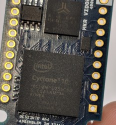
The FPGA on board the Arduino Vidor is an Altera Cyclone 10CL016. This chip has 16k logic elements, and 504 kB memory block. This is on the low end of Altera’s FPGA lineup, but it’s still no slouch. In the demo video below, it’s shown decoding video and identifying QR codes in real time. That’s pretty good for what is effectively a My First FPGA™ board.

Also on board the Vidor is a SAMD21 Cortex-M0+ microcontroller and a uBlox module housing an ESP-32 WiFi and Bluetooth module. This is a really great set of chips, and if you’re looking to get into FPGA development, this might just be the board for you. We haven’t yet seen the graphic editor that will be used to work with IP for the FPGA (for those who don’t care to write their own VHDL or Verilog), but we’re looking forward to the unveiling of that new software.

Today ahead of the Bay Area Maker Faire, Arduino has announced a bevy of new boards that bring modern features and modern chips to the Arduino ecosystem.

Most ambitious of these new offerings is a board that combines a fast ARM microcontroller, WiFi, Bluetooth, and an FPGA. All this is wrapped in a package that provides Mini HDMI out and pins for a PCIe-Express slot. They’re calling it the Arduino MKR Vidor 4000.

Bringing an FPGA to the Arduino ecosystem is on the list of the most interesting advances in DIY electronics in recent memory, and there’s a lot to unpack here. FPGA development boards aren’t new. You can find crates of them hidden in the storage closet of any University’s electronics lab. If you want to buy an FPGA dev board, the Terasic DE10 is a good starter bundle, the iCEstick has an Open Source toolchain, and this one has pink soldermask. With the release of the MKR Vidor, the goal for Arduino isn’t just to release a board with an FPGA; the goal is to release a tool that allows anyone to use an FPGA.

The key to democratizing FPGA development is Arduino’s work with the Arduino Create ecosystem. Arduino Create is the company’s online IDE that gives everyone the ability to share projects and upload code with Over-the-Air updates. The MKR Vidor will launch with integration to the Arduino Create ecosystem that includes a visual editor to work with the pre-compiled IP for the FPGA. That’s not to say you can’t just plug your own VHDL into this board and get it working; that’s still possible. But Arduino would like to create a system where anyone can move blocks of IP around with a tool that’s easy for beginners.

A Facelift for the Uno WiFi

First up is the brand new Arduino Uno WiFi. While there have been other boards bearing the name ‘Arduino Uno WiFi’ over the years, a lot has changed in the world of tiny radio modules and 8-bit microcontrollers over the past few years. The new Arduino Uno WiFi is powered by a new 8-bit AVR, the ATMega4809. The ATMega4809 is a new part announced just a few months ago, and is just about what you would expect from the next-generation 8-bit Arduino; it runs at 20MHz, has 48 kB of Flash, 6 kB of SRAM, and it comes in a 48-pin package. The ATMega4809 is taking a few lattices of silicon out of Microchip’s playbook and adds Custom Configurable Logic. The CCL in the new ATMega is a peripheral that is kinda, sorta like a CPLD on chip. If you’ve ever had something that could be more easily done with logic gates than software, the CCL is the tool for the job.

But a new 8-bit microcontroller doesn’t make a WiFi-enabled Arduino. The wireless power behind the new Arduino comes from a custom ESP-32 based module from u-blox. There’s also a tiny crypto chip (Microchip’s ATECC508A) so the Uno WiFi will work with AWS. The Arduino Uno WiFi will be available this June.

But this isn’t the only announcement from the Arduino org today. They’ve been hard at work on some killer features for a while now, and now they’re finally ready for release. What’s the big news? Debuggers. Real debuggers for the Arduino that are easy to use. There are also new boards aimed at Arduino’s IoT strategy.

The Future of Arduino
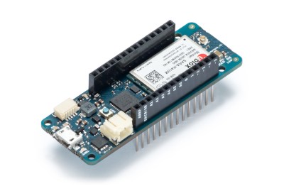
As you would expect in the world of embedded development, the future is IoT. Last week, Arduino announced the release of two new boards, the MKR WiFi 1010 and the MKR NB 1500. The MKR WiFi 1010 features a SAMD21 Cortex-M0+ microcontroller and a u-blox module (again featuring an ESP-32) giving the board WiFi. The MKR NB 1500 is designed for cellular networks and features the same SAMD21 Cortex-M0+ microcontroller found in the MKR WiFi 1010, but also adds a u-blox cellular module that will connect to LTE networks using Narrowband IoT, but the module does also support Cat M1 networks.

But IoT isn’t the only thing Arduino has been working on. On the leadup to the World Maker Faire this weekend, I had the opportunity to speak with Fabio Violante, CEO of Arduino, and Massimo Banzi, Co-founder of Arduino, and what I heard was remarkable. There’s going to be an update to the Arduino IDE soon, and real debugging is coming to the Arduino ecosystem. This is a significant development in Arduino’s software efforts, and when Fabio was appointed CEO last July, this was the first thing he wanted to do.

Also on deck for upcoming bits of hardware is a slow upgrade from ARM Cortex-M0 parts to Cortex-M4 parts. While this change isn’t exactly overdue, it is a direct result of the ever-increasing power of available microcontrollers. The reason for this change is the growing need for more compute power on embedded platforms, and simply the fact that more powerful chips are cheaper now.

Massimo, Fabio, and the rest of the Arduino team will be showing off their latest wares at Maker Faire Bay Area this weekend, and we will be posting updates. The FPGA Arduino — the MKR Vidor 4000 — will be on display running a computer vision demo, and there will, of course, be fancy new boards on hand. We’ll be posting updates so keep your eye on Hackaday!

Alorium rolled out a new product late last year that caught our attention. The Sno (pronounced like “snow”) board is a tiny footprint Arduino board that you can see in the video below. By itself that isn’t that interesting, but the Sno also has an Altera/Intel Max 10 FPGA onboard. If you aren’t an FPGA user, don’t tune out yet, though, because while you can customize the FPGA in several ways, you don’t have to.

Like Alorium’s XLR8 product, the FPGA comes with preprogrammed functions and a matching Arduino API to use them. In particular, there are modules to do analog to digital conversion, servo control, operate NeoPixels, and do floating point math.

However, you can reprogram the FPGA to have other functions — known as XBs or Xcelerator Blocks — if you like. The only problem we see is that, so far, there aren’t many of them. In addition to the stock XBs, there is one that will do quadrature decoding for dealing with things like shaft encoders. There are a few others you can find on their GitHub page. You can get an idea for the workflow by looking at this tutorial for the XLR8 board.

Of course, you can write your own FPGA configurations as you see fit, but they also provide a standard workflow — OpenXLR8 — that lets you build your own blocks that operate just like their blocks. It would be easy to imagine an “app store” concept where people develop custom blocks and make them available.

We really like the idea of this device and it is certainly inexpensive. You can prototype on the XLR8 which looks like a UNO or you can put headers in the Sno. They also sell a breakout board that will make the Sno physically more like an UNO. We are surprised, though, that there are not more XBs created over the last two years.

The FPGA onboard is similar to the one on the Arrow board we looked at earlier this year, although that has some additional components like SDRAM. If you are looking for a project, it might be interesting to convert our PWM code into an XB.

Thanks to [K5STV] for showing us one of these.

What would you get it you mashed up an FPGA and an Arduino? An FPGA development board with far too few output pins? Or a board in the form-factor of Arduino that’s impossible to program?

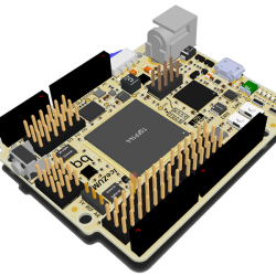
Fortunately, the ICEZUM Alhambra looks like it’s avoided these pitfalls, at least for the most part. It’s based on the Lattice iCE40 FPGA, which we’ve covered previously a number of times because of its cheap development boards and open-source development flow. Indeed, we were wondering what the BQ folks were up to when they were working on an easy-to-use GUI for the FPGA family. Now we know — it’s the support software for an FPGA “Arduino”.

Icezum-rev1-1607-img1-peq_thumbnail

The Alhambra board itself looks to be Arduino-compatible, with the horrible gap between the rows on the left-hand-side and all, so it will work with your existing shields. But they’ve also doubled them with pinheaders in a more hacker-friendly layout: SVG — signal, voltage, ground. This is great for attaching small, powered sensors using a three-wire cable like the one that you use for servos. (Hackaday.io has two Arduino clones using SVG pinouts: in SMT and DIP formats.)

The iCE40 FPGA has 144 pins, so you’re probably asking yourself where they all end up, and frankly, so are we. There are eight user LEDs on the board, plus the 28 I/O pins that end in pinheaders. That leaves around a hundred potential I/Os unaccounted-for. One of the main attractions of FPGAs in our book is the tremendous availability of fast I/Os. Still, it’s more I/O than you get on a plain-vanilla Arduino, so we’re not complaining too loudly. Sometimes simplicity is a virtue. Everything’s up on GitHub, but not yet ported to KiCad, so you can tweak the hardware if you’ve got a copy of Altium.

We’ve been seeing FPGA projects popping up all over, and with the open-source toolchains making them more accessible, we wonder if they will get mainstreamed; the lure of reconfigurable hardware is just so strong. Putting an FPGA into an Arduino-compatible form-factor and backing it with an open GUI is an interesting idea. This project is clearly in its very early stages, but we can’t wait to see how it shakes out. If anyone gets their hands on these boards, let us know, OK?

Thanks [RS] for the tip!


Filed under: Arduino Hacks, FPGA

Some things are better together: me and my wife, peanut butter and jelly, and FPGAs and Arduino Unos. Veteran hacker [Valentin Angelovski] seems to agree: the FleaFPGA Uno is his latest creation that combines an FPGA (a Lattice MachX02 700HC) with an Arduino-compatible CPU.

It’s a step-up model from the origional FleaFPGA. With a few other components thrown in (such as a HDMI and composite video output and a WiFi option), you have a killer combination for experimenting with FPGAs or building an embedded system. That is because the Arduino part frees the FleaFPGA Uno from the breadboard: you can easily program, control and interface with the FPGA over a serial line or a wireless link using the Arduino IDE. There is even support for Arduino shields (albeit only 3.3V ones), making it even more expandable. This would be an awesome starting point for a retro gaming system, as many 8-bit consoles can be easily emulated in an FPGA. [Valentin] is currently selling the boards directly, and they are very reasonably priced at $50 or $60 for the WiFi version.


Filed under: Arduino Hacks, FPGA

The new XLR8 board.The XLR8 is an FPGA based board that looks and feels like an Arduino Uno. But not all is what it seems on the surface.

Read more on MAKE

The post XLR8 Project Blends FPGA Speed with Arduino Coding appeared first on Make: DIY Projects, How-Tos, Electronics, Crafts and Ideas for Makers.

Mar
05

A Low Cost Arduino FPGA Shield

altium, arduino, arduino hacks, FPGA Comments Off on A Low Cost Arduino FPGA Shield 

ardu-fpga

[technolomaniac] is kicking butt over at Hackaday Projects. He’s creating a low cost Arduino based FPGA shield. We’ve seen this pairing before, but never with a bill of materials in the $25 to $30 range. [technolomaniac's] FPGA of choice is a Xilinx Spartan 6. He’s also including SDRAM, as well as an SPI Flash for configuration. Even though the Spartan 6 LX9 is a relatively small FPGA, it can pack enough punch that the Arduino almost becomes a peripheral. The main interconnect between the two will be the Arduino’s ability to program the Spartan via SPI. Thanks to the shared I/O pins though, the sky is the limit for parallel workflow.

[technolomaniac] spent quite a bit of time on his decoupling schematic. Even on a relatively small FPGA power decoupling is a big issue, especially when high speed signals come into play. Thankfully Xilinx provides guides for this task. We have to mention the two excellent videos [technolomaniac] created to explain his design. Documenting a project doesn’t have to be hours of endless writing. Sometimes it’s just easier to run a screen capture utility and click record. As of this writing, the schematic has just been overhauled, and [technolomaniac] is looking for feedback before he enters the all important layout stage. The design is up on his github repository in Altium format. Due to its high cost, Altium isn’t our first pick for Open Hardware designs. There are free viewers available, but [technolomaniac] makes it simple by putting up his schematic in PDF format (PDF link). Why not head over to projects and help him out?


Filed under: Arduino Hacks
Jul
15

Filtering out mains hum from ADC samples

ADC, arduino hacks, dsp, FPGA, mains hum Comments Off on Filtering out mains hum from ADC samples 

Hum_filter

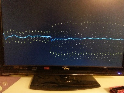
A little light reading means something different to us than it does to [Hamster]. He’s been making his way through a book called The Scientist and Engineer’s Guide to Digital Signal Processing written by [Steven W. Smith, Ph.D]. Being the hacker type, a million different uses for the newfound knowledge popped to mind. But as a sanity check he decided to focus on a useful proof of concept first. He’s come up with a way to filter out the mains hum from Analog to Digital Converter samples.

Mains hum is all around us; produced by the alternating current in the power grid that runs our modern lives. It’s a type of interference that can be quite problematic, which is on reason why we see EMF sensor projects from time to time. Now you can filter that ambient interference from your projects which take readings from an ADC. This would be quite useful for applications which measuring teeny signals, like ECG hacks.

[Hamster] did a pretty good job of presenting his demonstration for the uninitiated. He even provides examples for Arduino or FPGA projects.


Filed under: Arduino Hacks, FPGA


  • Newsletter

    Sign up for the PlanetArduino Newsletter, which delivers the most popular articles via e-mail to your inbox every week. Just fill in the information below and submit.

  • Like Us on Facebook