
Jul
04
04

.jpg)
Turnigy TGY-SM-3317SR 360? Analog Robot Servo 2.2kg / 86RPM / 19g
Took the electronics from two of these and connected them to the servo motors to control the mirrors


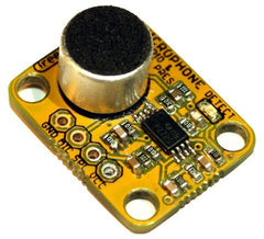
Freetrioncs Microphone Sound Input Module
Russian blue cat
I found this cat really helped with the programming

Very simple sketch
#include

Servo myservo1; // create servo object to control a servo
Servo myservo2;

int patterns[] =
{
 92,88,
 70,85,
 60,85,
 80,85,
 85,85,
 70,85,
 85,0,
 85,110,
 85,115,
 70,88,
 5,30,
 135,45,
 92,88,
 180,0,
 50,100,
 85,85,
 100,105,
 70,0,
 75,0,
 105,115
};

int NumPatterns = 0;


int laserPin = 3;      // LED connected to digital pin 9
int ledPin = 4;      // LED connected to digital pin 9
int MicPin = 1;   // potentiometer connected to analog pin 3
int LevelPin = 0;
int pos = 0;    // variable to store the servo position

int val = 0;         // variable to store the read value
int val2 = 0;
int tick = 500;
int TickMod = 500;
int Sweep = 0;
int LaserPWM = 0;
int LaserPWMvector = 1;

int Mirror1 = 0;
int Mirror2 = 0;

int Mic = 0;
int Level = 0;

int LevelIndex = 0;
int LevelBuf[200] = {0, };
int LevelMean = 0;

int LevelValueIndex = 0;
int LevelValueBuf[10] = {0, };

int ShutOffBits = 50;
int Active = 0;


void setup()
{
  Serial.begin(9600);

  pinMode(laserPin, OUTPUT);   // sets the pin as output
  pinMode(ledPin, OUTPUT);   // sets the pin as output
  myservo1.attach(8);  // attaches the servo on pin 9 to the servo object
  myservo2.attach(9);  // attaches the servo on pin 9 to the servo object

  pos = 30;
  myservo1.write(pos);

  pos = 95;
  myservo2.write(pos);

  digitalWrite(laserPin, HIGH);

  randomSeed(analogRead(0));

  NumPatterns = sizeof(patterns);

}

void loop()
{
   tick++;

   Mic = analogRead(MicPin);

   LevelMean = CalcLevelMean();

   Level = CalcLevelValue();

    if(LevelMean > ShutOffBits)
      Active = 1;
    else
      Active = 0;

    if((tick % 10) == 0)
    {
       //LaserPWM += LaserPWMvector;
       val = abs(Level - LevelMean);
       if(val < 1) val = 1;
       if(val > 5) val = 5;

       if(LaserPWMvector > 0)
         LaserPWM += val;
       else
         LaserPWM -= val;

       if(LaserPWM < 0) { LaserPWM = 0;  LaserPWMvector = 1; StepPattern("PWM == 0n");}
       if(LaserPWM > 255){ LaserPWM = 255; LaserPWMvector = 0-1; }
    }

    val = LaserPWM;

    if(Active > 0)
      analogWrite(laserPin, val);  // analogRead values go from 0 to 1023, analogWrite values from 0 to 255
    else
      digitalWrite(laserPin, LOW);

    //val = map(abs(Level - 512), 0, 512, 0, 255);

    //analogWrite(ledPin, val);


    if((tick % 100) == 0)
      SendData("");

    //if(abs(Level - 512) > 100)
    //  StepPattern("LOUD");

    delayMicroseconds(1000);

    if((tick % 100) == 0)
      SetMirrors("");


}


void StepPattern(char* txt)
{

    Sweep += 2;
    if(Sweep > (NumPatterns - 2)) Sweep = 0;

}

 void SetMirrors(char* txt)
 {

    if(Active > 0)
    {
        val = random(0,100);

        //Serial.print("nRANDOM: ");
        //Serial.print(val);
        //Serial.print("n");

        if(val > 500)
        {
          val = abs(Level - LevelMean) + (Mic - 512);

          val = map(val, 0, 512, 0, 20);

          Serial.print("MUSIC:");
          Serial.print(val);

          pos=90+val;
          myservo1.write(pos);

          pos=90-val;
          myservo2.write(pos);


        }
        else
        {
          //Serial.print("nSWEEPn");

          val2 = abs(Level - LevelMean);


          pos = Mirror1;

          val = (patterns[Sweep] - Mirror1) /10;

          if(val < 1) val = 1;

          pos += val;

          pos = patterns[Sweep] + val2;

          myservo1.write(pos);

          Mirror1 = pos;


          pos = Mirror2;

          val = (patterns[Sweep + 1] - Mirror2) /10;

          if(val < 1) val = 1;

          pos += val;

          pos = patterns[Sweep + 1] - val2;

          myservo2.write(pos);

          Mirror2 = pos;

        }

    }
    else
    {
        pos = 90;
        myservo1.write(pos);
        myservo2.write(pos);
    }

    //SendData(txt);
}

void SendData(char* txt)
{
    if(strlen(txt) > 0)
    {
      Serial.print("n");
      Serial.print(txt);
      Serial.print("n");
    }

    Serial.print("Sweep:");
    Serial.print( Sweep);

    Serial.print("tLevel - LevelMean: ");
    Serial.print(abs(Level - LevelMean));

    Serial.print("tMirror1 & Mirror2: ");
    Serial.print( Mirror1);
    Serial.print("  ");
    Serial.print( Mirror2);


    Serial.print("tLaserPWMvector:");
    Serial.print( LaserPWMvector);
    Serial.print("tLaserPWM:");
    Serial.print( LaserPWM);
    Serial.print("tLevelMean:");
    Serial.print(  LevelMean);
    Serial.print("tLevel:");
    Serial.print(analogRead(LevelPin));
    Serial.print("tmic:");
    Serial.print(analogRead(MicPin));
    Serial.print("n");

}

int CalcLevelMean()
{

  LevelBuf[LevelIndex] = analogRead(LevelPin);

  if((++LevelIndex) > 199)
    LevelIndex = 0;

    double ltot = 0.0;
    for(int i = 0;i < 200;i++)
      ltot += (double)LevelBuf[i];

    return (int)(ltot / 200.0);
}

int CalcLevelValue()
{

  LevelValueBuf[LevelValueIndex] = analogRead(LevelPin);

  if((++LevelValueIndex) > 10)
    LevelValueIndex = 0;

    double ltot = 0.0;
    for(int i = 0;i < 100;i++)
      ltot += (double)LevelValueBuf[i];

    return (int)(ltot / 100.0);
}


