While it seems like Nixie tubes get all the attention when it comes to making retro-style displays, there are plenty of other display technologies that can make a good-looking retro design. Take the Numitron tube: introduced by RCA in the early 1970s, these display tubes might look superficially similar to Nixies but work in a completely different way. The Numitron uses incandescent elements that make up seven-segment displays.
The main advantage Numitrons have over Nixes is that they don’t require a high-voltage supply, which makes them much easier to hook up to modern low-voltage electronics. [mircemk] used this to his advantage when he built a simple clock using four numitrons that can display the time, the date, and the ambient temperature.
The brains of the device are formed by an Arduino Nano coupled with a DS3231 battery-backed real-time clock module. For now, the time has to be synchronized by connecting the Arduino to a PC and reprogramming it, but [mircemk] has plans to update the design with pushbuttons to allow the user to set the time manually.
Four shift registers are all that’s needed to interface the microcontroller to the display tubes, thanks to their low-voltage operation. They do need quite a lot of current, so [mircemk] used the high-power TPIC6C595 instead of a regular 74HC595 chip. We wonder if the tubes’ high power consumption could be the reason why the temperature in his lab seems to hover around 30 °C.
A simple but stylish plastic enclosure completes the design. Since Numitron tubes are relatively low-cost and no other specialized components are needed, this could be one of the cheapest and easiest ways to make a retro display tube clock. Although we’ve seen a couple of Numitron clocks and even watches before, today’s build is a great example of how simple such a design can actually be.
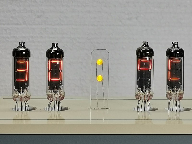
In this article we examine another style of vintage display technology – the incandescent seven-segment digital display. We are using the FFD51 by the IEE company (data sheet.pdf) – dating back to the early 1970s. Here is a close-up of our example:
You can see the filaments for each of the segments, as well as the small coiled ‘decimal point’ filament at the top-right of the image above. This model has pins in a typical DIP format, making use in a solderless breadboard or integration into a PCB very simple:
It operates in a similar manner to a normal light bulb – the filaments are in a vacuum, and when a current is applied the filament glows nicely. The benefit of using such as display is their brightness – they could be read in direct sunlight, as well as looking good inside. At five volts each segment draws around 30mA. For demonstration purposes I have been running them at a lower voltage (3.5~4V), as they are old and I don’t want to accidentally burn out any of the elements.
Using these with an Arduino is very easy as they segments can be driven from a 74HC595 shift register using logic from Arduino digital out pins. (If you are unfamiliar with doing so, please read chapters four and five of my tutorial series). For my first round of experimenting, a solderless breadboard was used, along with the usual Freetronics board and some shift register modules:
Although the modules are larger than a DIP 74HC595, I like to use these instead. Once you solder in the header pins they are easier to insert and remove from breadboards, have the pinouts labelled clearly, are almost impossible to physically damage, have a 100nF capacitor for smoothing and a nice blue LED indicating power is applied.
Moving forward – using four shift register modules and displays, a simple four-digit circuit can be created. Note from the datasheet that all the common pins need to be connected together to GND. Otherwise you can just connect the outputs from the shift register (Q0~Q7) directly to the display’s a~dp pins.
Some of you may be thinking “Oh at 30mA a pin, you’re exceeding the limits of the 74HC595!”… well yes, we are. However after several hours they still worked fine and without any heat build-up. However if you displayed all eight segments continuously there may be some issues. So take care. As mentioned earlier we ran the displays at a lower voltage (3.5~4V) and they still displayed nicely. Furthermore at the lower voltage the entire circuit including the Arduino-compatible board used less than 730mA with all segments on – for example:
For the non-believers, here is the circuit in action:
Here is the Arduino sketch for the demonstration above:
Now for the prototype of something more useful – another clock. Time to once again pull out my Arduino-compatible board with onboard DS1307 real-time clock. For more information on the RTC IC and getting time data with an Arduino please visit chapter twenty of my tutorials. For this example we will use the first two digits for the hours, and the last two digits for minutes. The display will then rotate to showing the numerical day and month of the year – then repeat.
Operation is simple – just get the time from the DS1307, then place the four digits in an array. The elements of the array are then sent in reverse order to the shift registers. The procedure is repeated for the date. Anyhow, here is the sketch:
and the clock in action:
So there you have it – another older style of technology dragged into the 21st century. If you enjoyed this article you may also like to read about vintage HP LED displays. Once again, I hope you found this article of interest. Thanks to the Vintage Technology Association website for background information.
Have fun and keep checking into tronixstuff.com. Why not follow things on twitter, Google+, subscribe for email updates or RSS using the links on the right-hand column, or join our Google Group – dedicated to the projects and related items on this website. Sign up – it’s free, helpful to each other – and we can all learn something.
Planet Arduino is, or at the moment is wishing to become, an aggregation of public weblogs from around the world written by people who develop, play, think on Arduino platform and his son. The opinions expressed in those weblogs and hence this aggregation are those of the original authors. Entries on this page are owned by their authors. We do not edit, endorse or vouch for the contents of individual posts. For more information about Arduino please visit www.arduino.cc
You are currently browsing the archives for the numitron category.