Posts | Comments

Planet Arduino

Archive for the ‘teardown’ Category

Coin-operated machines have a longer history than you might think. Ancient temples used them to dispense, for example, holy water to the faithful in return for their coins. Old payphones rang a bell when you inserted a coin so the operator knew you paid. Old pinball machines had a wire to catch things with holes in the middle so you couldn’t play with washers. But like everything else, coin acceptors have advanced quite a bit. [Electronoobs] shows a unit that can accept coins from different countries and it is surprisingly complex inside. He used what he learned from the teardown to build his own Arduino-based version.

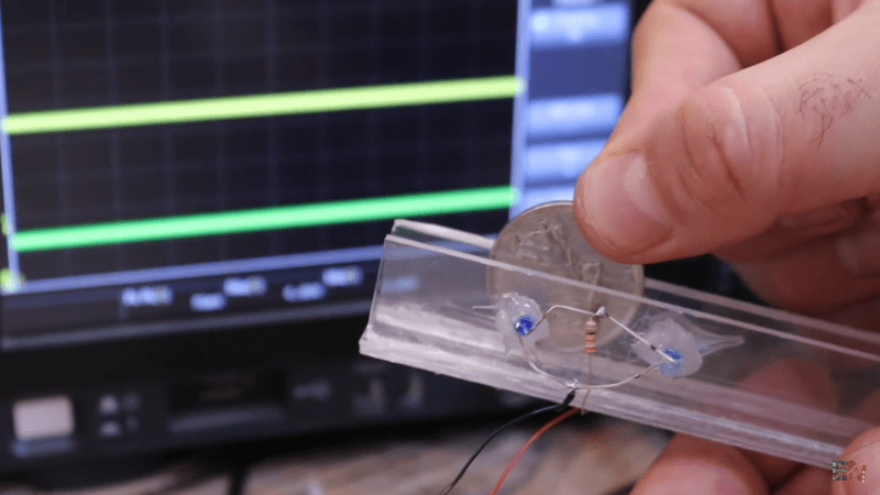
For scale, there is the obligatory banana. Inside the box there are several induction coils and some photo electronics. In particular, there are two optical sensors that watch the coin roll down a ramp. This produces two pulses. The width of the pulse indicates the diameter of the coin, and the time between the pulses tells its speed.

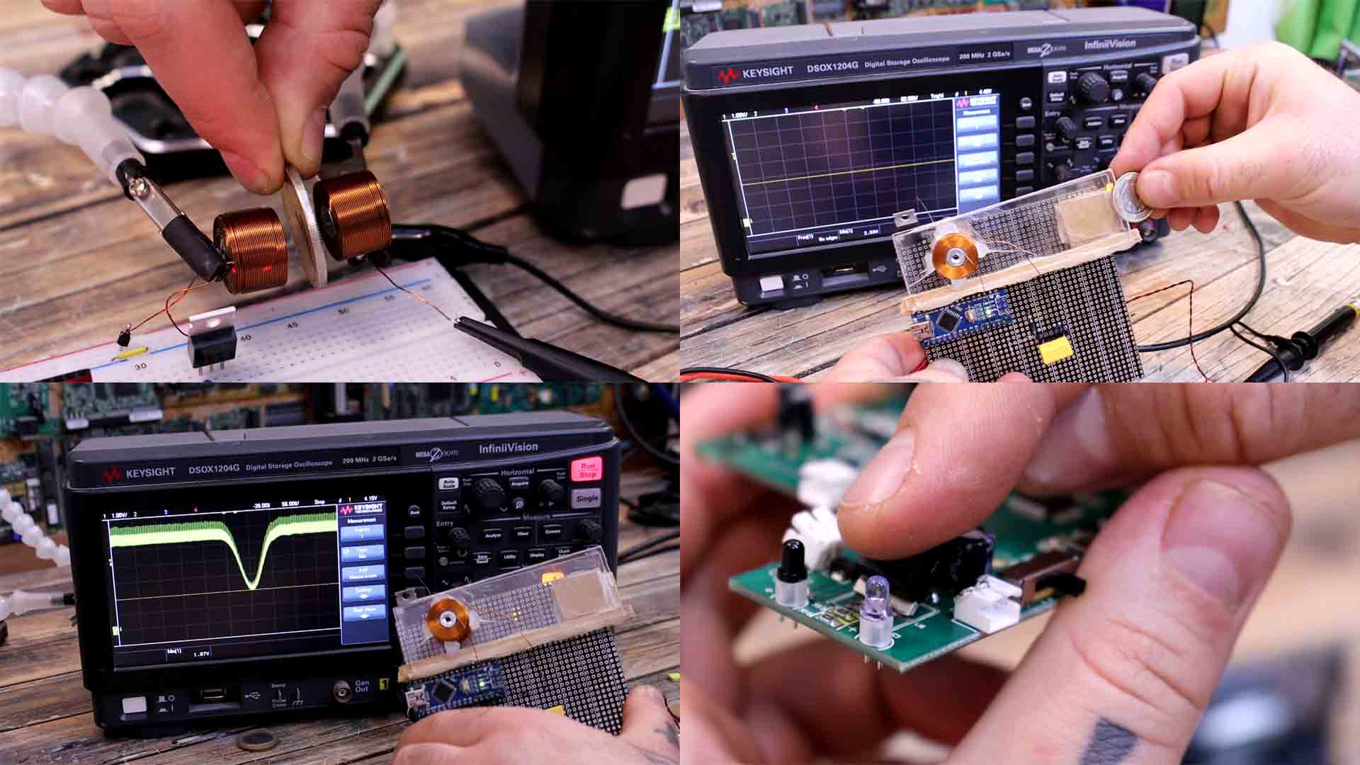
So what are the two coils for? They form a transformer, and the coin moving between the coils changes the coupling in a way that depends on the material. By knowing the diameter, the transit speed of the coin, and the material, you can identify the coin. A little solenoid-driven flap moves out of the way to store a recognized coin. If it doesn’t move out of the way, the coin goes out of the coin return slot.

We wondered how the machine knows about local currency and what happens if the composition of a coin changes. The video shows how you teach the device about a coin by inserting a sample coin multiple times and letting the device measure. So even if you had some custom token, it should work.

The homebrew solution is pretty easy, especially the optical part. The coils are a bit more work since you need a big coil along with the associated driver and sense electronics. Then, of course, there is also the mechanics, which he did not build, since the commercial product was only $20.

We always enjoy teardowns, but this one was especially informative, and we enjoyed the reproduction of the operating principles. Hero was a Greek who lived a long time ago and would have really been interested in this teardown. We couldn’t help but think, too, of [Peter’s] coin-operated calculator.

Introduction

Time for something different – and perhaps the start of several new articles containing teardowns. In our first instalment we examine the Tektronix CFC250 100 MHz frequency counter circa 1994: Not the most spectacular of designs, but it has worked well right until the present day. The update speed of the display wasn’t lightning fast, however for the time it would have been quite reasonable. Here is a short video I shot last year comparing it against a small frequency counter kit:

However after staring at this thing every day on my desk for a couple of years it has now become impossible to overcome the temptation to have a look inside. Therefore the reason for this article. You can click on the images to see the full-size version. So let’s go back to 1988 and check out the CFC250…

External tour

A quick look around the outside. The casing is reminiscent of the Escort brand of test equipment from the era, and (I suspect that) they OEM’d the CFC250 for Tektronix. (Interestingly enough Agilent bought the assets of Escort in 2008). Moving forward, the external images of the CFC250 starting with the front:

… and the rear. The AC transformer is tapped out to accept four different mains voltages, which you can select with the slide switches:

Opening up the unit involves removing screws from the base. The first ones were only for the feet, so they could stay put:

It was the screw on the right of the foot that was the key to entry. After removing them from each side and the other pair on the rear-bottom, the top casing pulls off easily…

Internal tour

… leaving us with the internals for all to see:

Although the LED display is a fair giveaway to the age of the CFC250,  a quick look around the PCB confirms it… and the display is ultimately controlled by an LSI Systems LS7031 “Six decade MOS up counter” (data sheet.pdf). It is matched to some DS75492N MOS-to-LED hex digit driver ICs (data sheet.pdf) and some other logic ICs. It is interesting to compare the number of parts required to drive the LEDs compared to a contemporary microcontroller and something like the TM1640 used in this module.

Now for the LED display board:

Nothing too out of the ordinary. A closer look at the rear panel shows some very neat AC mains wiring:

Now for some more close-ups. Here we can see the use of the MM5369 17-stage oscillator/divider (data sheet.pdf). I haven’t seen one of these for a while, the last time we used them was for a 60Hz timebase. However in this case it would be used to create an accurate timebase within which the CFC250 would count the number of incoming pulses:

 The removal of two more screws allows removal of the main PCB from the base of the cabinet, which reveals as such:

There is also an opaque plastic sheet cut to fit, helping insulate the PCB from the rest of the world:

 The PCB is single-sided and very easy to follow. I wonder if it was laid out by hand?

It reminds me of some old kits from the past decade.  Moving forward, there is a metal shield around the PCB area of signal input and low-pass filter:

A quick desolder of three points allows removal of the shield, and reveals the following:

At the top-left of the above image reveals a resistor in a somewhat elevated position, as shown below:

If anyone can explain this one, please leave a comment below.

 Conclusion

What impressed me the most during this teardown was the simple way in that the unit was designed – all through-hole parts, mechanical connections either soldered or nuts and bolts, and all components labelled. I can imagine that during the lifespan of the CFC250 it would have been relatively simple to repair. Such is the price of progress. And yes, it worked after putting it all back together again.

In the meanwhile, full-sized original images are available on flickr. I hope you found this article of interest. Coming soon we will have some more older-technology items to examine and some new tutorials as well.

In the meanwhile, have fun and keep checking into tronixstuff.com. Why not follow things on twitterGoogle+, subscribe  for email updates or RSS using the links on the right-hand column, or join our Google Group – dedicated to the projects and related items on this website. Sign up – it’s free, helpful to each other –  and we can all learn something.

The post Tektronix CFC250 Teardown appeared first on tronixstuff.


  • Newsletter

    Sign up for the PlanetArduino Newsletter, which delivers the most popular articles via e-mail to your inbox every week. Just fill in the information below and submit.

  • Like Us on Facebook