[Christopher Mitchell] has given Texas Instruments calculators the ability to capture images through a Game Boy Camera with ArTICam. First introduced in 1998, The Game Boy Camera was one of the first low-cost digital cameras available to consumers. Since then it has found its way into quite a few projects, including this early Atmel AT90 based hack, and this Morse code transceiver.
TI calculators don’t include a Game Boy cartridge slot, so [Christopher] used an Arduino Uno to interface the two. He built upon the Arduino-TI Calculator Linking (ArTICL) Library to create ArTICam. Getting the Arduino to talk with the Game Boy Camera’s M64282FP image sensor turned out to be easy, as there already are code examples available. The interface between the camera sensor and the Arduino is simple enough. 6 digital lines for an oddball serial interface, one analog sense line, power and ground. [Christopher] used a shield to solder everything up, but says you can easily get away with wiring directly the Arduino Uno’s I/O pins. The system is compatible with the TI-83 Plus and TI-84 Plus family of calculators. Grabbing an image is as simple as calling GetCalc(Pic1) from your calculator program.
So, If you have an old calculator lying around, give it a try to enjoy some 128×123-pixel grayscale goodness!
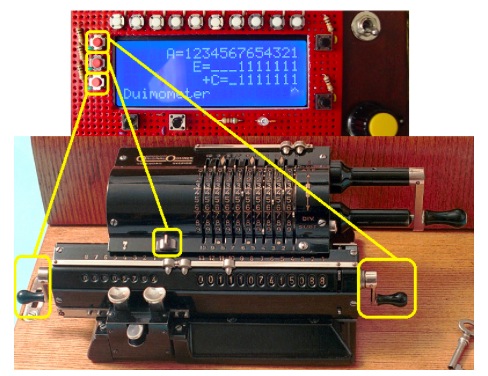
The Odhner Arithmometer was a very popular pinwheel calculator invented in Russia in 19th century by a Swedish immigrant called W. T. Odhner. Like most of pinwheel calculators, it worked with an engine formed by a set of linked wheels which could perform the four basic mathematical operations within a machine of reduced size.
Diego Cueva worked on a diy emulator called Duimometer, made with Arduino UNO. See how it works in the video below and look at the sketch here.
It’s no secret that I enjoy kit reviews – it’s always interesting to see how well a kit goes together, along with the quality of parts, documentation and so on. But what about kits from the past? And not 2003. Recently a very rare opportunity to purchase a sealed Sinclair Radionics Cambridge calculator kit appeared on ebay – so it was ordered rapidly and duly delivered to the office. And thus the subject of this review.
You may be familiar with the Sinclair name – Sir Clive Sinclair introduced many innovative and interesting products to the UK and world markets in his own style. Some were a raging success, such as the ZX-series home computers – and some were not. However in 1973 Sinclair introduced a range of calculators, starting with the “Cambridge”. It’s a simple four-function calculator with an LED numeric display and a somewhat dodgy reputation.
The design evolved rapidly and at the Mark III stage it was sold assembled and as a kit. At the time handheld calculators were quite expensive, so the opportunity to save money and get one in kit form would have been quite appealing to the enthusiast – in January 1974 the kit retailed in the UK for 24.95 (+ VAT):
Assembly
Putting the Cambridge together required a balance of healthy paranoia, patience and woodworker mentality (measure twice – cut once). There wouldn’t be any second chances, or quick runs down to Altronics for a replacement part (well … there was one) so care needed to be taken. If you’re curious about the details, I’ve uploaded 82 full-resolution images from the build, including both instruction manuals and schematic onto flickr. Now to get started.
The kit arrives in a neat, retail-orientated package:
… with the components on one side of the foam:
… and the other side held he assembly guide (underneath which was a very short length of solder and the carrying case):
At this point I was starting to have doubts, and thought it would be better off in storage. But what fun would that be? So out with the knife and the shrink-wrap was gone, revealing the smell of 1974 electronics. Next to whip out the instructions and get started:
They are incredibly detailed, and allow for two variations of enclosure and also offer tips on good construction – as well as the schematic, BOM and so on. Like any kit it’s wise to take stock of the components, which gave us the PCB:
… the passives, diodes and transistor – and some solder wick:
At this point it turned out the all but one of the resistors were anywhere near the specified values in the instructions, and I wasn’t going to trust those electrolytic capacitors after 39 years. The replacement parts were in stock – including the original 1n914 diode that was missing from the kit. Thanks Clive. There was also a coil of unknown value:
… and the ICs, which included the brains of the operation – a General Instrument Microelectronics CZL-550:
… and an ITT 7105N:
… a bag of battery clips, buttons and adhesive-backed foam (which deteriorated nicely):
At this point it was time to fire up the Hakko and start soldering, not before giving the PCB a good hit with the Servisol cleaner spray. I was worried about the tracks lifting while soldering due to heat and old-age, however the PCB held up quite well. The first step is to solder in the clips that hold (just) four AAA cells:
… then the resistors and diodes:
… followed by the transistor, ITT IC, ceramic capacitor and coil:
Uh-oh – that ceramic went in the wrong hole. One leg was soldered where the coil was to sit. Without wanting to damage the PCB, de-soldering it was a slow, slow process. Then of course I didn’t have a ) 3.3nF in stock, so a quick spin to Altronics solved that problem (I bought 50) – one of which finally went in:
The transistor was also a bit of a puzzle, I hadn’t seen that enclosure type and the manual wasn’t much help, so the semiconductor analyser tester solved that problem:
The next step was to fit the display, which is wedged in the large gap at the top of the PCB. The tracks on the PCB are supposed to meet the display, however time had affected the tracks on the display module, so I soldered small wire links across the gaps:
Following the display were the two (new) electrolytics:
And now to the main IC. There wasn’t any second chances with this, and after some very gently pin-bending it dropped in nicely:
After a short break it was time to assemble the keypad, which went smoothly. After cleaning all the foam dust off the buttons, they dropped in to their frame which in turn dropped into the enclosure, followed by the keypad layers:
You can also see in the display window and shroud have been fitted. From here the PCB is inserted:
… and a sticker from years gone by, as well as the metal clip over the bottom of the power switch. At this point a quick test with four AAA cells showed signs of life on the display, so the rear enclosure could be fitted:
Now for the battery and final cover, and it’s ready to go!
The digits are quite sharp, but very small – and set back from the window. This makes photography quite difficult. At the time if your calculator didn’t work, you could send it off to Sinclair and they’d repair or possibly replace it for you:
Using the Cambridge
Well it works, so you have a calculator which is genuinely useful. However the Cambridge has a few quirks, which are attributed to the basic functions of the main IC. For example, when entering numbers the screen is filled with leading zeros until you select a function, however by using the manual you can complete complex work including square roots, percentages, loan repayments and much more.
Furthermore the Cambridge is quite the silent achiever, you can work with numbers as small as 1x10E-20 and up to 9.9999999E79. You simply enter the numbers in decimal form (e.g. 0.000000000123) … even though the display won’t show all the digits, they’re being stored in a register. To then extract the result, you continually multiply or divide by ten (making note of how many times you do that) until the digits appear on the screen. It sounds nuts today – but in 1974 it would have been a cheap way of avoiding a more expensive calculator. In the following video you can see th Cambridge in action, plus the results of dividing by zero:
More about Sinclair
The following video is a BBC dramatisation of the rise of the home computer in the UK market, and the competition between Sir Clive Sinclair (Sinclair) and Adam Curry (Acorn Computers) – which is quite entertaining:
You can find out more about the history of Sir Clive Sinclair here, and the calculator range here. If anyone can connect us with a Science of Cambridge MK14 computer, contact us.
Conclusion
From a 1974 perspective, that would have been a great kit to make, with some love and care it would have been successful. By today’s standards it was quite average – however you can’t really judge it from a 2013 perspective. Nevertheless, kudos to Sir Clive Sinclair for his efforts in knocking out a useful product as a kit. If you’re a collector, and see a sealed unit on ebay or elsewhere, give it a whirl. Just take your time, “think before doing”, and replace as many of the components as possible. I’ve put all the images in full resolution up on flickr, so you can follow along in more detail.
And while you’re here – are you interested in Arduino? Check out my new book “Arduino Workshop” from No Starch Press.
In the meanwhile have fun and keep checking into tronixstuff.com. Why not follow things on twitter, Google+, subscribe for email updates or RSS using the links on the right-hand column? And join our friendly Google Group – dedicated to the projects and related items on this website. Sign up – it’s free, helpful to each other – and we can all learn something.
In this article we examine a five digit, seven-segment LED display from Hewlett-Packard, the 5082-7415:
According to the data sheet (HP 5082-series.pdf) and other research this was available for a period of time around 1976 and used with other 5082-series modules in other HP products. Such as the Hewlett-Packard 3x series of calculators, for example:
Using the display is very easy – kudos to the engineers at HP for making a simple design that could be reusable in many applications. The 5082-7415 is a common-cathode unit and wiring is very simple – there are the usual eight anodes for segments a~f and the decimal point, and the five cathodes.
As this module isn’t too easily replaceable, I was very conservative with the power supply – feeding just under 1.6V at 10mA to each of the anode pins. A quick test proved very promising:
Excellent – it worked! But now to get it displaying some sort of interesting way. Using the following hardware…
… it was connected in the same method as a four-digit display (except for the extra digit) as described in my tutorial. Don’t forget to use the data sheet (HP 5082-series.pdf). You don’t have to use Arduino – any microcontroller with the appropriate I/O can take care of this.
Here is a simple Arduino sketch that scrolls through the digits with and then without the decimal point:
And the results:
Now for something more useful. Here is a function that sends a single digit to a position on the display with the option of turning the decimal point on or off:
So if you wanted to display the number three in the fourth digit, with the decimal point – use
with the following result:
We make use of the displayDigit() function in our next sketch. We introduce a new function:
It accepts a long integer between zero and 99999 (number) and displays it on the module for cycles times:
For demonstration purposes the sketch displays random numbers, as shown in the video below:
Update – 23/04/2012
Finally after some more hunting around I found some four-digit (possible knock-off versions of the) HP QDSP-6064 display units on eBay (item #120876219746) as shown below:
They worked very nicely and can be driven in the same method as the 5082-7415s descibed earlier. In the following video we have run the same sketches with the new displays:
Have fun and keep checking into tronixstuff.com. Why not follow things on twitter, Google+, subscribe for email updates or RSS using the links on the right-hand column, or join our Google Group – dedicated to the projects and related items on this website. Sign up – it’s free, helpful to each other – and we can all learn something.
Planet Arduino is, or at the moment is wishing to become, an aggregation of public weblogs from around the world written by people who develop, play, think on Arduino platform and his son. The opinions expressed in those weblogs and hence this aggregation are those of the original authors. Entries on this page are owned by their authors. We do not edit, endorse or vouch for the contents of individual posts. For more information about Arduino please visit www.arduino.cc
You are currently browsing the archives for the calculator category.


 David J Hicks, http://www.hpmuseum.org/")


