Today’s commercial aircraft are packed to the elevators with sensors, computers, and miles and miles of wiring. Inside the cockpit you’re more than likely to see banks of LCDs and push buttons than analog gauges. So what’s that mean for the intrepid home simulator builder? Modern problems require modern solutions, and this 3D printed simulator is about as modern as it gets.
Published to Thingiverse by the aptly named [FlightSimMaker], this project consists of a dizzying number of 3D-printed components that combine into a full-featured desktop simulator for the Garmin G1000 avionics system. Everything from the parking brake lever to the push buttons in the display bezels was designed and printed: over 200 individual parts in all. Everything in this X-Plane 11 compatible simulator is controlled by an Arduino Mega 2560 with the SimVim firmware.
To help with connecting dozens of buttons, toggle switches, and rotary encoders to the Arduino, [FlightSimMaker] uses five CD74HC4067 16-channel multiplexers. The display is a 12.1 inch 1024 x 768 LCD panel with integrated driver, and comes in at the second most expensive part of the build behind the rotary encoders. All told, the estimated cost per display is around $250 USD.
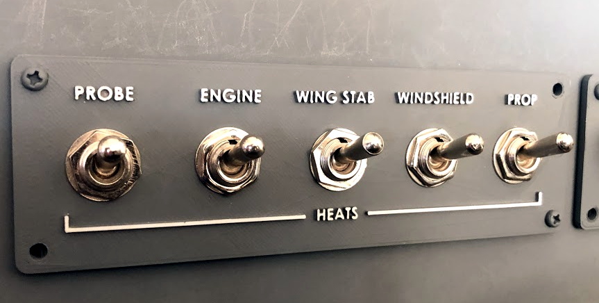
Even if you aren’t looking to build yourself a high-tech flight simulator, there’s plenty of ideas and tips here that could be useful for building front panels. We particularly like the technique used for doing 3D-printed lettering: the part is printed in white, spray painted a darker color, and then the paint is sanded off the faces of the letters to reveal the plastic. Even with a standard 0.4 mm nozzle, this results in clean high-contrast labels on the panel with minimal fuss.
After booting up his RetroPie system, [jfrmilner] had the distinct feeling that something was off. Realizing that the modern Xbox 360 controller didn’t fit right when reliving the games of his youth, he rounded up all his old controllers to make sure he always had the right gamepad for the game.
Wanting to keep the controllers unmodified — so they could still be used on the original systems — he had to do a bit of reverse-engineering and source some controller sockets before building his controller hub. Using shift-in registers, shift-out registers, and some multiplexers, he designed a large circuit selector — which acts as a shield for an Arduino Micro — so all the controllers remain connected. A potentiometer allows him to select the desired controller and a few arcade buttons which access RetroPie shortcuts really round out the hub. Check out the demo after the break!
[jfrmilner] kept the controllers relevant to the games he would be playing, but we hope there’s some room to include a controller in rug format in his build. Of course, there’s always the option of Jerry-rigging old systems to use your preferred retro gamepad.
[Alex] needed a project for his microcomputer circuits class. He wanted something that would challenge him on both the electronics side of things, as well as the programming side. He ended up designing an 8 by 16 grid of LED’s that was turned into a game of Tetris.
He arranged all 128 LED’s into the grid on a piece of perfboard. All of the anodes were bent over and connected together into rows of 8 LED’s. The cathodes were bent perpendicularly and forms columns of 16 LED’s. This way, if power is applied to one row and a single column is grounded, one LED will light up at the intersection. This method only works reliably to light up a single LED at a time. With that in mind, [Alex] needed to have a very high “refresh rate” for his display. He only ever lights up one LED at a time, but he scans through the 128 LED’s so fast that persistence of vision prevents you from noticing. To the human eye, it looks like multiple LED’s are lit up simultaneously.
[Alex] planned to use an Arduino to control this display, but it doesn’t have enough outputs on its own to control all of those lights. He ended up using multiple 74138 decoder/multiplexer IC’s to control the LED’s. Since the columns have inverted outputs, he couldn’t just hook them straight up to the LED’s. Instead he had to run the signals through a set of PNP transistors to flip the logic. This setup allowed [Alex] to control all 128 LED’s with just seven bits, but it was too slow for him.
His solution was to control the multiplexers with counter IC’s. The Arduino can just increment the counter up to the appropriate LED. The Arduino then controls the state of the LED using the active high enable line from the column multiplexer chip.
[Alex] wanted more than just a static image to show off on his new display, so he programmed in a version of Tetris. The controller is just a piece of perfboard with four push buttons. He had to work out all of the programming to ensure the game ran smoothly while properly updating the screen and simultaneously reading the controller for new input. All of this ran on the Arduino.
Can’t get enough Tetris hacks? Try these on for size.
Now and again there’s a need to expand the I/O capabilities of your chosen micorocontroller, and instead of upgrading you can often use external parts to help solve the problem. One example of this is the 74HC4067 16-channel analog multiplexer demultiplexer. That’s a mouthful – however in simple form it’s an IC that can direct a flow of current in either direction from one pin to any one of sixteen pins. Another way to think abou it is that you can consider the 74HC4067 to be a digital replacement to those rotary switches that allow you to select one of sixteen positions.
Here’s an example of the SMD version:
Don’t let that put you off, it’s just what we had in stock at the time. The part itself is available in through-hole and surface mount versions.
Using the 74HC4067
At this point you should download the data sheet, as we refer to it through the course of the article. The first thing to note is that the 74HC4067 can operate on voltages between 2 and 6V DC, which allows use with 3.3V and 5V microcontrollers and boards such as Arduino and Raspberry Pi. If for some reason you have the 74HCT4067 it can only work on 4.5~5.5V DC. Next – consider the pinout diagram from the data sheet:
The power supply for the part is applied to pin 24, and GND to … pin 12. Pin 15 is used to turn the control the current flow through the inputs/outputs – if this is connected to Vcc the IC stops flow, and when connected to GND it allows flow. You can always control this with a digital output pin if required, or just tie it to GND if this doesn’t matter.
Next – pin one. This is where the current either flows in to be sent to one of the sixteen outputs – or where the current flows out from one of the sixteen inputs. The sixteen inputs/outputs are labelled I0~I15. Finally there are the four control pins – labelled S0~S3. By setting these HIGH or LOW (Vcc or GND) you can control which I/O pins the current flow is directed through. So how does that work? Once again – reach for the the data sheet and review the following table:
Not only does it show what happens when pin 15 is set to HIGH (i.e. nothing) it shows what combination of HIGH and LOW for the control pins are required to select which I/O pin the current will flow through. If you scroll down a bit hopefully you noticed that the combination of S0~S3 is in fact the binary equivalent of the pin number – with the least significant bit first. For example, to select pin 9 (9 in binary is 1001) you set the IC pins S0 and S3 to HIGH, and S1 and S2 to LOW. How you control those control pins is of course up to you – either with some digital logic circuit for your application or as mentioned earlier with a microcontroller.
Limitations
Apart from the power supply requirements, there are a few limitations to keep in mind. Open you data sheet and consider the “DC Electrical Specifications” table. The first two parameters show what the minimum voltage that can be considered as a HIGH and the maximum for a LOW depending on your supply voltage. The next item of interest is the “ON” resistance – that is the resistance in Ohms (Ω) between one of the sixteen inputs/outputs and the common pin. When a channel is active, and a 5V supply voltage, we measured a resistance of 56Ω without a load through that channel – and the data sheet shows other values depending on the current load and supply voltage. Finally, don’t try and run more than 25 mA of current through a pin.
Examples
Now to show an example of both multiplexing and demultiplexing. For demonstration purposes we’re using an Arduino Uno-compatible board with the 74HC4067 running from a 5V supply voltage. Pin 15 of the ’4067 is set to GND, and control pins S0~S3 are connected to Arduino digital output pins D7~D4 respectively.
Multiplexing
This is where we select one input pin of sixteen and allow current to flow through to the common pin (1). In this example we connect the common pin to the board’s analog input pin – so this can be used as a method of reading sixteen analog signals (one at a time) using only one ADC. When doing so – take note of the limitations mentioned earlier – take some resistance measurements in your situation to determine what the maximum value will be from your ADC and calibrate code accordingly.
With both of the examples we’ll use port manipulation to control the digital pins which are connected to the 74HC4067′s control pins. We do this as it reduces the code required and conceptually I feel it’s easier. For example – to select I/O 15 you need to turn on all the control pins – so you just have to set Arduino PORTD to B11110000 (which is binary 15 LSB first) and much neater than using four digitalWrite() functions.
In the following example sketch, you can see how we’ve put the binary values for each control possibility in the array byte controlPins[] – which is then used to set the pins easily in void loop().
This simply sets each input pin in turn, then reads the ADC value into an array – whose values are then sent to the serial monitor:
// 74HC4067 multiplexer demonstration (16 to 1)

// control pins output table in array form
// see truth table on page 2 of TI 74HC4067 data sheet
// connect 74HC4067 S0~S3 to Arduino D7~D4 respectively
// connect 74HC4067 pin 1 to Arduino A0
byte controlPins[] = {B00000000,
                  B10000000,
                  B01000000,
                  B11000000,
                  B00100000,
                  B10100000,
                  B01100000,
                  B11100000,
                  B00010000,
                  B10010000,
                  B01010000,
                  B11010000,
                  B00110000,
                  B10110000,
                  B01110000,
                  B11110000 };

// holds incoming values from 74HC4067
byte muxValues[] = {0,0,0,0,0,0,0,0,0,0,0,0,0,0,0,0,};

void setup()
{
  Serial.begin(9600);
  DDRD = B11111111; // set PORTD (digital 7~0) to outputs
}

void setPin(int outputPin)
// function to select pin on 74HC4067
{
  PORTD = controlPins[outputPin];
}

void displayData()
// dumps captured data from array to serial monitor
{
  Serial.println();
  Serial.println("Values from multiplexer:");
  Serial.println("========================");
  for (int i = 0; i < 16; i++)
  {
    Serial.print("input I");
    Serial.print(i);
    Serial.print(" = ");
    Serial.println(muxValues[i]);
  }
  Serial.println("========================");
}

void loop()
{
  for (int i = 0; i < 16; i++)
  {
    setPin(i); // choose an input pin on the 74HC4067
    muxValues[i]=analogRead(0); // read the vlaue on that pin and store in array
  }

  // display captured data
  displayData();
  delay(2000);
}
… and a quick video of the results:
Demultiplexing
Now for the opposite function – sending current from the common pin to one of sixteen outputs. A fast example of this is by controlling one of sixteen LEDs each connected to an output pin, and with 5V on the 74HC4067 common pin. We don’t need current-limiting resistors for the LEDs due to the internal resistance in the 74HC4067. Here’s the sketch:
// 74HC4067 demultiplexer demonstration (1 to 16)

// control pins output table in array form
// see truth table on page 2 of TI 74HC4067 data sheet
// connect 74HC4067 S0~S3 to Arduino D7~D4 respectively
// 5V to 74HC4067 pin 1 to power the LEDs :)
byte controlPins[] = {B00000000,
                      B10000000,
                      B01000000,
                      B11000000,
                      B00100000,
                      B10100000,
                      B01100000,
                      B11100000,
                      B00010000,
                      B10010000,
                      B01010000,
                      B11010000,
                      B00110000,
                      B10110000,
                      B01110000,
                      B11110000 };

void setup()
{
  DDRD = B11111111; // set PORTD (digital 7~0) to outputs
}

void setPin(int outputPin)
// function to select pin on 74HC4067
{
  PORTD = controlPins[outputPin];
}

void loop()
{
  for (int i = 0; i < 16; i++)
  {
    setPin(i);
    delay(250);
  }
}
… and the LEDs in action:
Conclusion
If you’re considering the 74HC4067 or hadn’t known about it previously, we hope you found this of interest. If you have any questions please leave them below or privately via the contact page. And if you made it this far – check out my new book “Arduino Workshop” from No Starch Press.
In the meanwhile have fun and keep checking into tronixstuff.com. Why not follow things on twitter, Google+, subscribe for email updates or RSS using the links on the right-hand column? And join our friendly Google Group – dedicated to the projects and related items on this website. Sign up – it’s free, helpful to each other – and we can all learn something.
Planet Arduino is, or at the moment is wishing to become, an aggregation of public weblogs from around the world written by people who develop, play, think on Arduino platform and his son. The opinions expressed in those weblogs and hence this aggregation are those of the original authors. Entries on this page are owned by their authors. We do not edit, endorse or vouch for the contents of individual posts. For more information about Arduino please visit www.arduino.cc
You are currently browsing the archives for the Multiplexer category.

 To help with connecting dozens of buttons, toggle switches, and rotary encoders to the Arduino, [FlightSimMaker] uses five CD74HC4067 16-channel multiplexers. The display is a 12.1 inch 1024 x 768 LCD panel with integrated driver, and comes in at the second most expensive part of the build behind the rotary encoders. All told, the estimated cost per display is around $250 USD.


