Posts | Comments

Planet Arduino

Archive for the ‘ATmega328P’ Category

3d printed tiny gym in a box with mirror and led strip lighting

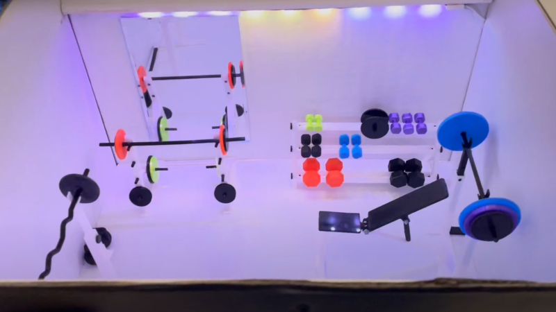
[Duncan McIntyre] lives in the UK but participated in a secret Santa gift exchange for his Dutch friends’ Sinterklaas celebration. In traditional maker fashion, [Duncan] went overboard and created a miniature gym gift box, complete with flashing lights, music and a motorized lid.

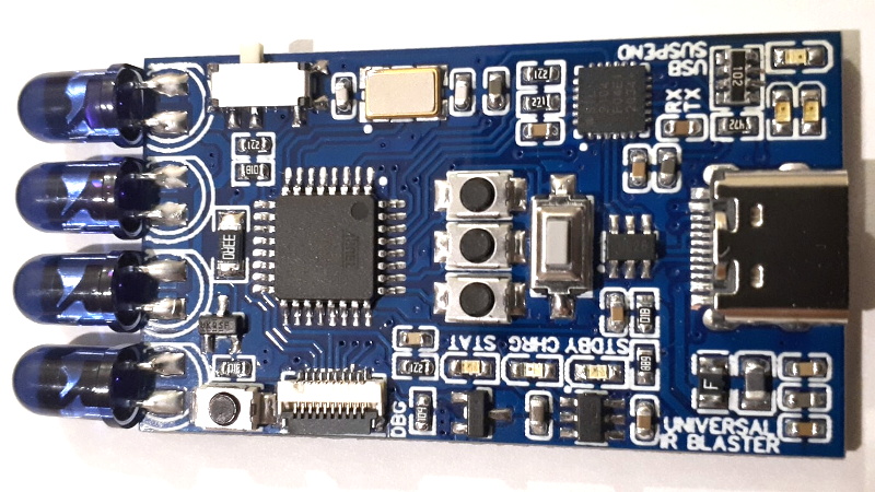
[Duncan] used [TanyaAkinora]’s 3D printed tiny gym to outfit the box with tiny equipment, with a tiny mirror added to round out the tiny room. An ATmega328P was used as the main microcontroller to drive the MP3 player module and A4988 stepper motor controller. The stepper motor was attached to a drawer slide via a GT2 timing belt and pulley to actuate the lid. Power is provided through an 18V, 2A power supply with an LM7805 providing power to the ATmega328P and supporting logical elements. As an extra flourish, [Duncan] added some hardware audio signal peak detection, fed from the speaker output, which was then sampled by the ATmega328P to be able to flash the lights in time with the playing music. A micro switch detects when the front miniature door is opened to begin the sequence of lights, song and lid opening.

[Duncan] provides source on GitHub for those curious about the Arduino code and schematics. We’re fans of miniature pieces of ephemera and we’ve featured projects ranging from tiny 3D printed tiny escalators to tiny arcade cabinets.

Video after the break!

The PCB business card has long been a way for the aspiring electronics engineer to set themself apart from their peers. Handing out a card that is also a two player game is a great way to secure a couple minutes of a recruiter’s time, so [Ryan Chan] designed a business card that, in addition to his contact information, also has a complete Tic-Tac-Toe game built in.

[Ryan] decided that an OLED display was too expensive for something to hand out and an LED matrix too thick, so he decided to keep it simple and use an array of 18 LEDs—9 in each of two colors laid out in a familiar 3×3 grid. An ATmega328p running the Arduino bootloader serves as the brains of the operation. To achieve a truly minimal design [Ryan] uses a single SMD pushbutton for control: a short press moves your selection, a longer press finalizes your move, and a several-second press switches the game to a single-player mode, complete with AI.

If you’d like to design a Tic-Tac-Toe business card for yourself, [Ryan] was kind enough to upload the schematics and code for his card. If you’re still pondering what kind of PCB business card best represents you, it’s worth checking out cards with an updatable ePaper display or a tiny Tetris game.

Thanks to [Abe] for the tip!

The TV-B-Gone is a well known piece of kit in hacker circles: just point it at a noisy TV in a public space, hit the button, and one of the hundreds of IR remote codes for “Power Off” that it blinks out in rapid succession is more than likely to get the intended response. Unfortunately, while a neat conversation starter, its practical use is limited to a single function. But not so with this programmable IR development board that creator [Djordje Mandic] describes as a “TV-B-Gone on steroids”.

Sure you can point it at a random TV and turn it off with a single button press, but you can also plug the board into your computer and control it directly through the serial connection provided by its CP2104 chip. Using a simple plain-text control protocol, the user can modify the behavior of the device and monitor its status. [Djordje] imagines this feature being used in conjunction with a smartphone application for covert applications. To that end, the device’s support for an onboard battery should keep it from draining the phone during extended operations.

Of course you could do something else entirely with it simply by firing up the Arduino IDE and writing some new code for the device’s ATmega328P microcontroller. As with the IR-enabled ESP8266 development board we looked at a few months ago, there are plenty of applications for an all-in-one board that allows you to communicate with the wide world of IR devices.

We’ve all seen those chess computers that consist out of a physical playing field, and a built-in computer that would indicate where you should put its pieces while inputting the position of your pieces in some way. These systems are usually found in a dusty cardboard box in a back room’s closet, as playing like this is fairly cumbersome, and a lot depends on the built-in chess computer.

This take by [andrei.erdei] on this decades-old concept involves an ATmega328p-based Arduino Pro Mini board, a nice wooden frame, and 4 WS2812-based 65×65 mm RGB 8×8 LED matrices, as well as some TTP223 touch sensors that allow one to control the on-board cursor. This is the sole form of input: using the UP and RIGHT buttons to select the piece to move, confirm with OK, then move to the new position. The chess program will then calculate its next position and indicate it on the LED matrix.

Using physical chess pieces isn’t required either: each 4×4 grid uses a special pattern that indicates the piece that occupies it.  This makes it highly portable, but perhaps not as fun as using physical pieces. It also kills the sheer joy of building up that collection of enemy pieces when you’ve hit that winning streak. You can look at the embedded gameplay video after the break and judge for yourself.

At the core of the chess program is [H.G. Muller]’s micro-Max project. Originally ported to the Arduino Uno, this program outputs the game to the serial port. After tweaking it to use the LED matrix instead, [andrei.erdei] was then faced with the lack of memory on the board for the most common LED libraries. In the end, the FAB_LED library managed to perform the task with less memory, allowing it and the rest of the program to fit comfortably into the glorious 2 kB of SRAM that the ATmega328p provides.

Classic 8-bit chess engines are marvels of software engineering. Ever wonder how they stack up against modern chess software? Check out this article!

We’ve all got calculators on our phones, in our web browsers, and even in the home “assistant” that’s listening in on your conversations all day on the off chance you blurt out a math question is can solve for you. The most hardcore among us might even still have a real calculator kicking around. So in that light, building your own DIY calculator might not seem too exciting. But we can’t deny this Arduino calculator project by [Danko Bertović] would look good sitting on the bench.

In the video after the break, [Danko] walks us through the creation of the calculator, from placing all the through-hole components to writing the code that pulls it all together. Special attention is given to explaining the wiring, making this is a good project for those just getting started on their digital hacking journey. It also helps that the whole thing is put together on perfboard with jumper wires; no PCB fabrication required for this one.

For the user interface, [Danko] is using an array of 17 tactile switches for the keyboard and a very crisp 128×32 I2C OLED display. Beyond the battery, a crystal, and a handful of passive components, that’s about all the support hardware it takes to put this project together. You don’t even need an enclosure: a second piece of perfboard and some standoffs are used to sandwich the battery and fragile wiring inside.

Of course, the star of the show is the ATmega328P microcontroller, which is mounted in a place of honor right under the OLED screen. The chip gets programmed in an Arduino Uno and then transplanted into the calculator, a neat trick if you don’t have a dedicated programmer handy. Given how cheap Arduino clones can be had online, this is becoming a more common practice.

The construction of this calculator reminds us a bit of the DIY Sinclair scientific calculator we looked at over the summer. But if you want to see the peak of homebrew calculator technology, this Raspberry Pi powered build is tough to beat.

A few months ago we brought word that [Electronoobs] was working on his own open source alternative to pocket-sized temperature controlled soldering irons like the TS100. Powered by the ATMega328p microcontroller and utilizing a 3D printed enclosure, his version could be built for as little as $15 USD depending on where you sourced your parts from. But by his own admission, the design was held back by the quality of the $5 replacement soldering iron tips he designed it around. As the saying goes, you get what you pay for.

But [Electronoobs] is back with the second version of his DIY portable soldering iron, and this time it’s using the vastly superior HAKKO T12 style tip. As this tip has the thermocouple and heating element in series it involved a fairly extensive redesign of the entire project, but in the end it’s worth it. After all, a soldering iron is really only as good as its tip to begin with.

This version of the iron deletes the MAX6675 used in V1, and replaces it with a LM358 operational amplifier to read the thermocouple in the T12 tip. [Electronoobs] then used an external thermocouple to compare the LM358’s output to the actual temperature at the tip. With this data he created a function which will return tip temperature from the analog voltage.

While the physical and electrical elements of the tip changed substantially, a lot of the design is still the same from the first version. In addition to the ATMega328p microcontroller, version 2.0 of the iron still uses the same 128×32 I2C OLED display, MOSFET, and 5V buck converter from the original iron. That said, [Electronoobs] is already considering a third revision that will make the iron even smaller by replacing the MOSFET and buck converter. It might be best to consider this an intermediate step before the DIY iron takes on its final form, which we’re very interested in seeing.

The first version of the DIY Arduino soldering iron garnered quite a bit of attention, so it seems there’s a decent number of you out there who aren’t content with just plunking down the cash for the TS100.

[Thanks to BaldPower for the tip.]

When you show up at a party wearing this bare PCB watch, there are effectively two possible reactions you might receive from the other people there. Either they are going to snicker at the nerd who’s wearing a blinking circuit board on their wrist in public, or they are going to marvel at the ridiculously low part count. We’ll give you one guess as to which reaction you’d likely get at any event Hackaday is involved in.

Designed and built by [Electronoobs], this extremely simple watch consists of a ATmega328P microcontroller, a dozen LEDs with their associated 200 Ω resistors, and a battery. There’s also a single push button on the front which is used to not only set the watch, but turn the LEDs on when you want to check the time. Short of dropping down to one LED and blinking out the time, it’s hard to imagine a timepiece with fewer components than this.

You’re probably wondering how [Electronoobs] pulled this off without an external clock source for the ATmega328P chip. The chip actually has an internal 8 MHz oscillator that can be used, but you need to flash the appropriate bootloader to it first. Accordingly, the backside of the PCB has both SPI and a UART solder pads for external bootloader and firmware programming.

As you might expect, there’s a downside to using the internal oscillator: it’s not very good. The ATmega328P spec sheet claims a factory calibrated accuracy of ±10%, and [Electronoobs] has found that equates to a clock drift of around 15 seconds per day. Not exactly great, but considering the battery only lasts for two days anyway, it doesn’t have much of an impact in this case.

Compared to other “analog” LED watches we’ve seen, the simplicity of this build is really quite remarkable. The closest competitor we’ve seen so far is this slick binary watch.

At this point you’ve almost certainly seen one of these low-cost portable soldering irons, perhaps best exemplified by the TS100, a pocket-sized temperature controlled iron that can be had for as little as $50 USD from the usual overseas suppliers. Whether or not you’re personally a fan of the portable irons compared to a soldering station, the fact remains that these small irons are becoming increasingly popular with hackers and makers that are operating on a budget or in a small workspace.

Believing that imitation is the most sincere form of flattery, [Electronoobs] has come up with a DIY portable soldering iron that the adventurous hacker can build themselves. Powered by an ATMega328p pulled out of an Arduino Nano, if offers the same software customization options of the TS100 but at a considerably lower price. Depending on where you source your components, you should be able to build one of these irons for as little as $15.

The iron features a custom PCB and MAX6675 thermocouple amplifier to measure tip temperature. A basic user interface is provided by two tactile buttons on the PCB as well as an 128×32 I2C OLED display. In a future version, [Electronoobs] says he will look into adding some kind of sensor to detect when the iron is actually being used and put it to sleep when inactive.

The tip is sourced from a cheap soldering station replacement iron, and according to [Electronoobs], is probably the weakest element of the entire build. He’s looking into using replacement TS100 tips, but says he’ll need to redesign his electronics to make it compatible. The case is a simple 3D printed affair, which looks solid enough, but seems likely to be streamlined in later versions.

We’ve seen a number of attempts at DIY soldering irons over the years, but we have to say, this one is probably the most professional we’ve ever seen. It will be interesting to see how future revisions improve on this already strong initial showing.

Small OLED displays are inexpensive these days–cheap enough that pairing them with an 8-bit micro is economically feasible. But what can you do with a tiny display and not-entirely-powerful processor? If you are [ttsiodras] you can do a real time 3D rendering. You can see the results in the video below. Not bad for an 8-bit, 8 MHz processor.

The code is a “points-only” renderer. The design drives the OLED over the SPI pins and also outputs frame per second information via the serial port.

As you might expect, 3D output takes a good bit of math, and the chip in question isn’t very good at handling real numbers. [Ttsiodras] handles this using an old technique: fixed point arithmetic. The idea is simple. Normally, we think of a 16-bit word as holding unsigned values of 0 – 65535. However, if you choose, you can also use it to represent numbers from 0-50.999, for example. Mentally, you scale everything by 1,000 and then reverse the operation when you want to output. Addition and subtraction are straightforward, but multiplication and division require some extra work.

If you want to read more about fixed point math, you are in the right place. We’ve also covered a great external tutorial, too. But if you think this is the first time we’ve covered a 3D graphics engine for the ATmega parts, you’re wrong.


Filed under: Arduino Hacks

goblin2_A

We are happy to announce another new member in the Arduino AtHeart Program! GOBLIN 2 from Mexican startup VERSE Technology is an Arduino-friendly development board with powerful wireless capabilities and broad compatibility with industrial protocols like RS-485.

Designed for both IoT professionals and Makers alike, GOBLIN 2 features an ATmega328P MCU and SIM5320A module at its core, providing dual-band HSDPA and quad-band GSM/GPRS/EDGE connectivity, along with high accuracy 16-channel GPS. The SIM5320A enables GOBLIN 2 to connect with web servers through any cellular network, and includes a header for keyboards, microphones, and speakers. 

GOBLIN 2 is equipped with six analog and 10 digital ports (half of them work as PWM), and offers 24V, 5V and 3.3V voltage outputs. The board is powered by a LiPo battery, which can be charged through micro-USB or solar cell thanks to its built-in battery management system. 

According to VERSE Technology CEO Aaron Benitex:

“We are developing technology to monitor and control the billions of present and future Internet of Things-ready devices. GOBLIN 2 is a board that allows our users to measure parameters like temperature, humidity, position, and others in remote locations. We have designed it in a way that it can easily work with industrial sensors and other applications such as telemetry, weather, GPS systems, and more.”

GOBLIN 2 can be programmed using the Arduino IDE as well as Atmel Studio. Simply upload your code to the board via micro USB, and begin exploring the IoT. Want to learn more? Check out VERSE Technology website


  • Newsletter

    Sign up for the PlanetArduino Newsletter, which delivers the most popular articles via e-mail to your inbox every week. Just fill in the information below and submit.

  • Like Us on Facebook