This little game has everything you could want from a splash screen introduction to a handy scoring guide on the silkscreen. After choosing the number of players, the first player rolls using the momentary button and the electronic dice light up to indicate what was rolled. As long as the player rolled at least one scoring die, they can take the points by selecting the appropriate die/dice with the capsense pads, and either pass or keep going. The current player’s score is shown on the 7-segment, and the totals for each player are on the OLED screen at the bottom.
The brains of the operation is an Arduino Pro Mini. It controls two MAX7219s that drive the 42 LEDs plus the 7-segment display. A game like this is all in the code, and lucky for us, [Sunyecz22] made it available. We love how gorgeous the glossy 3D printed enclosure looks — between the glossy finish and the curved back, it looks very comfortable to hold. In the future, [Sunyecz22] plans to make a one player versus the computer mode. Check out the demo and walk-through video after the break.
The capsense modules are a great touch, but some people want a little more tactility in their handheld games. We say bring on the toggle switches.
Fans of D&D are surely aware of the significance of a good pair of dice. What if your dice were not only stylish, but smart? For anyone who’s ever had to deal with playing board games with less than reputable siblings or friends, the electric die just might be your savior.
The dice are configured via Bluetooth, tracking rolls and stats over the course of gameplay captured by an accelerometer.
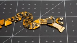
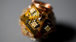
The PCB had to have a flexible surface – specifically in the shape of an unfolded icosahedron – in order to form the shape of the die which constrains the design to two layers. Each face contains an LED facing outwards to light up the number on that side. The LEDs are directly powered by a rechargeable battery, which uses a small coil for wireless inductive charging. Rather than opting for a Qi charger chipset, which regulates the maximum amount of power transmitted if the efficiency falls below a threshold, [Jean Simonet] uses a simpler charger setup using a full bridge rectifier, capacitors, and a linear regulator to create a stable 5V supply for the receiving end.
While the initial design for the die required an injection molded plastic shell, an easier solution was to simply cast the designs in resin. The electronics are placed into a dice mold and cast just as a regular die would be.
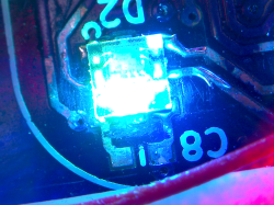
This luckily also solved the issue of needing to fit the components inside a screw-on container with a removable lid, which presented a hassle in terms of finding a battery that would fit the dimensions. The LEDs – purchased for cheap on Alibaba – are daisy chained to reduce the complexity of the routing.
One issue with the LEDs, however, is that the internal PWMs modulating the intensity remain on even at an intensity of 0, constantly drawing 21 mA (for the 21 LEDs on the die). This causes the battery to die after 2-3 hours. The solution [Simonet] used was to add a transistor to cut off power to the LEDs and to have the MCU toggle the transistor when the LEDs are turned off. Even this solution didn’t solve the entire problem since the LEDs still drain current from the data and clock lines, so those lines had to be low before going to sleep.
There were some stability issues with using a small buck converter to bring the LiPo voltage down to 3.3V, so the power regulation was done directly by the MCU instead. Switching the die off is controlled by a magnetic switch connected to a power buck converter that turns off logic when a magnet is present. This initially caused the LED control lines to become floating when power was turned off, turning the LEDs to arbitrary colors. The solution was to wire the output of the magnetic sensor to the MCU and to allow the software to handle the LEDs as well.
Maybe it’s because creator [Simonet] happens to be a game developer as well, but the early development stages of the electronic die (CAD, circuit schematics, prototyping, hand soldering components) were streamed on Twitch, adding some interactivity to even the build phase. The end result may be small, but these dice certainly have large brains!
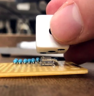
There are truisms about dice that you’ve probably already heard: if you have just one of them it’s called a “die”, opposite faces of each die always add up to seven, and those dots that you’re adding together are known as “pips”. But what about the infrared properties of those pips? It turns out they reflect less IR than the white body of the die and that trait can be used to build an automatic die reader.
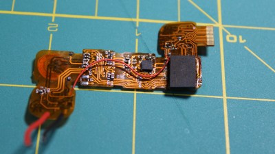
Great projects have a way of bubbling to the surface. The proof of concept comes from way back in 2009, and while the source blog is now defunct, it’s thankfully been preserved by the Internet Archive. In recreating the project based on that barebones description, [Calvin] reached for a set of five IR transmitter/receiver pairs. Take a close look and you’ll see each transmitter is hidden under its partnered receiver. The light shines up through the receiver and bounces off the pip, or doesn’t if the pip is missing.
This board is only the sensor portion of the design. A 595 shift register provides the ability to control which IR pair is powered, plus five more signals heading out to the analog pins of an Arduino Uno to monitor how much light is being detected by the receivers. Hey, that’s another interesting fact about dice, you only need to read five different pips to establish the value shown!
We wish there were a demo video showing this in action, but alas we couldn’t find one. We were amused to hear [Calvin] mentioned this was a sorting assignment at University and the team didn’t want to build yet another candy sorter. Look, we love an epic M&M sorter just as much as the next electronic geek, but it’s pretty hard to one-up this dice-based random number generator which rolls 1.3 million times each day.
For fun and a little bit of learning, let’s make a Larson Scanner. This isn’t a new project, for example we reviewed a kit in the past – however after finding some large LEDs we decided to make our own version. We’ll use an Arduino-compatible circuit to control the LEDs, and explain both the hardware and required Arduino sketch – then build a temporary small and a more permanent large version (and a bonus project).
So what is a Larson Scanner anyway? Named in honour of Glen A. Larson the creator of television shows such as Battlestar Galactica and Knight Rider – as this kit recreates the left and right blinking motion used in props from those television shows. For example:
Making your own is quite simple, it’s just eight LEDs or lamps blinking in a certain order. If you’re not familiar with the Arduino hardware, please have a quick review of this tutorial before continuing.
Small version
If you’re just interested in whipping up a solderless breadboard or small version, it will take less than fifteen minutes. Just get an Arduino Uno or compatible board and construct the following circuit (the resistors are 560Ω):
The sketch is also very simple. There are two ways to address those digital output pins, and to save sanity and clock cycles we’re going to use port manipulation instead of many digitalWrite() functions. So for our circuit above, enter and upload the following sketch:
// Simple Arduno LED back-and-forth effects, similar to "KITT" from "Knight Rider"
// Original idea by Glen A. Larson
// Arduino sketch - John Boxall 2013

int del=75; // delay between LED movements

void setup()
{
  DDRD = B11111111; // D0~D7 outputs
}

void loop()
{
  PORTD = B00000001;
  delay(del);
  PORTD = B00000011;
  delay(del);
  PORTD = B00000111;
  delay(del);
  PORTD = B00001110;
  delay(del);
  PORTD = B00011100;
  delay(del);
  PORTD = B00111000;
  delay(del);
  PORTD = B01110000;
  delay(del);
  PORTD = B11100000;
  delay(del);
  PORTD = B11000000;
  delay(del);
  PORTD = B10000000;
  delay(del);
  PORTD = B11000000;
  delay(del);
  PORTD = B11100000;
  delay(del);
  PORTD = B01110000;
  delay(del);
  PORTD = B00111000;
  delay(del);
  PORTD = B00011100;
  delay(del);
  PORTD = B00001110;
  delay(del);
  PORTD = B00000111;
  delay(del);
  PORTD = B00000011;
  delay(del);
}
Notice how the ones and zeros in the byte send to PORTD (digital pins 7~0) represent the “movement” of the scanner? You’d have to agree this is a better method of addressing the LEDs. Have some fun and experiment with the patterns you can generate and also the delay. In the following video we’ve quickly demonstrated the circuit on a solderless breadboard using different delay periods:
Large Version
Now to make something more permanent, and much larger. There are many ways of completing this project, so the following version will be a design narrative that you can follow to help with planning your own. The first consideration will be the LEDs you want to use. For our example we used some Kingbright DLC2-6SRD 20mm bright red versions we had in stock:
However you can use what you have available. The key to success will be driving the LEDs at their maximum brightness without damage. So you need to find out the best forward voltage and current for the LEDs, then do some basic mathematics. From our example LEDs’ data sheet, the maximum brightness is from 60 mA of current, at just under 6 V. A quick connection to a variable power supply shows the LEDs at this setting:
We can’t get this kind of brightness from our Arduino 5V circuit, so instead we’ll increase the circuit supply voltage to 9V and use resistors to reduce the current for the LEDs. To find the resistor value, use the following:
… where Vs is the supply voltage (9), VLED is the forward voltage for the LED (5.6), and ILED is the forward current (60 mA). The value for R is 56.66 Ω – however you can’t get that value, so 68 Ω will be the closest value from the supplier. Finally, the power of the resistor required (in watts) is calculated by W = VA. So W = 3.4 (voltage drop over resistor) * 0.06 = 0.204 W. So we’ll need 68 Ω 0.25 W resistors for our LEDs. Thus instead of running the LED straight off a digital output, it will be switched on and off via a simple BC548 transistor – shown in the following schematic example:
The digital output for each LED is connected to the 1k Ω resistor and thus switches the transistor on to allow the current to flow through the LED when required. This is repeated for each LED we intend to use – which for the case of our large scanner project is six. (Why six? Someone bought a board which was too narrow for eight…) Next is the Arduino-compatible circuit. Timing isn’t critical so we’ll save components by using a ceramic resonator instead of a crystal and two capacitors. And as shown below (note that although the image on the microcontroller says ATmega168, we’ll use an ATmega328P):
(If you’re not up for making your own Arduino-compatible circuit, there’s plenty of alternative small boards you can use such as the Nano or LeoStick). Although the symbol for Y1 (the resonator) looks complex, it’s just a resonator – for example:
the centre pin goes to GND and the outside pins go to XTAL1 and XTAL2 on the microcontroller. It isn’t polarised so either direction is fine.
At this point you may also want to consider how you’ll upload and update sketches on the project. One method is to mount the microcontroller in a socket, and just yank it between an Arduino board to upload the sketch, and then put it back in the project board. If you use this method then you’ll need a microcontroller with the Arduino bootloader. However a more civilised method is to add ICSP header pins – they’re the 2 x 3 pins you see on most boards, for example:
With which you can use a USBASP programmer to connect your board directly to a computer just like a normal Arduino. Just use Ctrl-Shift-U to upload your sketch via the programmer. Furthermore you can use bare microcontrollers without the bootloader, as all the necessary code is included with the direct upload. So if this method interests you, add the following to your circuit:
The RESET pin is connected to pin 1 of the microcontroller. Speaking of which, if you’re unsure about which pins on the ATmega328P are which, a variety of suppliers have handy labels you can stick on top, for example:
At this point it’s time to put it all together. We’re using a random piece of prototyping PCB, and your final plan will depend on your board. As an aside, check out the Lochmaster stripboard planning software if you use stripboard a lot. As mentioned earlier your final schematic will vary depending on the number of LEDs, their requirements with respect to current and your choice of Arduino platform. By now you have the knowledge to plan the circuit yourself. After some work here’s our final board:
… and the scanner in action. We used the same sketch as for the temporary version – however reduce it to six outputs (D0~5) to match the LEDs.
Bonus project – Electronic Die
What else can you do with six LEDs? Make an electronic die! Here’s a simple sketch that simply picks a random number every five seconds. The random number generator is seeded from unused an analogue input pin.
// Simple Arduno LED die using Larson Scanner hardware described in http://wp.me/p3LK05-36m
// John Boxall 2013

int del=5000; // delay between new rolls
int num;

byte  digits[] = { B00000001,
                   B00000010,
                   B00000100,
                   B00001000,
                   B00010000,
                   B00100000 };

void setup()
{
  randomSeed(analogRead(0)); // reseed the random number generator with some noise
  DDRD = B11111111; // D0~D7 outputs
}

void rollDie()
{
  for (int i = 0; i< 20; i++)
  {
    num = random(0,6);
    PORTD = digits[num];
    delay(50);
  }
}

void pickNumber()
{
  num = random(0,5);
  PORTD = digits[num];
  delay(1000);
}

void loop()
{
  rollDie();
  pickNumber();
}
And a quick video of our die in action:
Conclusion
We hope you found this interesting and at least made a temporary scanner on a breadboard – or at least learned something. Kudos if you went ahead and made a larger one. If you made a video, share it with us in the comments. And if you made it this far – check out my new book “Arduino Workshop” from No Starch Press.
In the meanwhile have fun and keep checking into tronixstuff.com. Why not follow things on twitter, Google+, subscribe for email updates or RSS using the links on the right-hand column? And join our friendly Google Group – dedicated to the projects and related items on this website. Sign up – it’s free, helpful to each other – and we can all learn something.
Planet Arduino is, or at the moment is wishing to become, an aggregation of public weblogs from around the world written by people who develop, play, think on Arduino platform and his son. The opinions expressed in those weblogs and hence this aggregation are those of the original authors. Entries on this page are owned by their authors. We do not edit, endorse or vouch for the contents of individual posts. For more information about Arduino please visit www.arduino.cc
You are currently browsing the archives for the dice category.