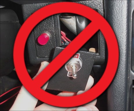
In the old days, a physical button or switch on the dashboard of your car would have been wired to whatever device it was controlling. There was potentially a relay in the mix, but still, it wasn’t too hard to follow wires through the harness and figure out where they were going. But today, that concept is increasingly becoming a quaint memory.
Assuming your modern car even has physical buttons, pushing one of them likely sends a message over the CAN bus that the recipient device will (hopefully) respond to. Knowing how intimidating this can be to work with, [TJ Bruno] has been working on some software that promises to make working with CAN bus user interfaces faster and easier. Ultimately, he hopes that his tool will allow users to rapidly integrate custom hardware into their vehicle without having to drill a hole in the dashboard for a physical control.
But if you’re the kind of person who doesn’t like to have things done for them (a safe bet, since you’re reading Hackaday), don’t worry. [TJ] starts off his write-up with an overview of how you can read and parse CAN messages on the Arduino with the MCP2515 chip. He breaks his sample Sketch down line by line explaining how it all works so that even if you’ve never touched an Arduino before, you should be able to get the gist of what’s going on.
As it turns out, reading messages on the CAN bus and acting on them is fairly straightforward. The tricky part is figuring out what you’re looking for. That’s where the code [TJ] is working on comes in. Rather than having to manually examine all the messages passing through the network and trying to ascertain what they correspond to, his program listens while the user repeatedly presses the button they want to identify. With enough samples, the code can home in on the proper CAN ID automatically.
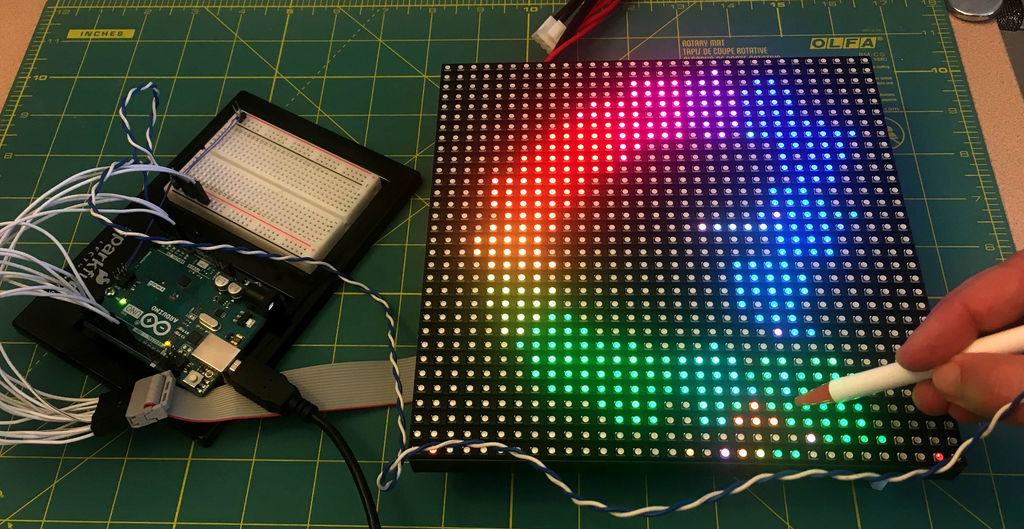
Consider that a digital camera uses an array of sensors to capture light from an object. Maker Marcio T, however, decided to turn this idea on its head and instead utilize an array of lights that are detected by a single sensor.
The way it works is that as each LED in a 32×32 matrix illuminates, a phototransistor picks up light if the path is clear or sees no change if the path is blocked. So when you put an object on the matrix, the sensor is able to get an accurate picture of it, enabling its Arduino Uno controller to then generate its silhouette.
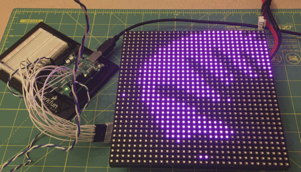
It’s a simple yet very clever hack, and if you pay close attention in the video below, you can see the lights scanning from the bottom to top before the image is produced.
Ordinary digital cameras work by using a large array of light sensors to capture light as it is reflected from an object. In this experiment, I wanted to see whether I could build a backwards camera: instead of having an array of light sensors, I have just a single sensor; but I control each of 1,024 individual light sources in a 32 x 32 LED matrix.
The way it works is that the Arduino illuminates one LED at a time, while using the analog input to monitor changes in the light sensor. This allows the Arduino to test whether the sensor can “see” a particular LED. This process is repeated for each of the 1,024 individual LEDs rapidly to generate a map of visible pixels.
If an object is placed between the LED matrix and the sensor, the Arduino is able to capture the silhouette of that object, which is lit up as a “shadow” once the capture is complete.
Do any of you stay awake at night agonizing over how the keytar could get even cooler? The 80s are over, so we know none of us do. Yet here we are, [James Cochrane] has gone out and turned a HP ScanJet Keytar for no apparent reason other than he thought it’d be cool. Don’t bring the 80’s back [James], the world is still recovering from the last time.
Kidding aside (except for the part of not bringing the 80s back), the keytar build is simple, but pretty cool. [James] took an Arduino, a MIDI interface, and a stepper motor driver and integrated it into some of the scanner’s original features. The travel that used to run the optics back and forth now produce the sound; the case of the scanner provides the resonance. He uses a sensor to detect when he’s at the end of the scanner’s travel and it instantly reverses to avoid collision.
A off-the-shelf MIDI keyboard acts as the input for the instrument. As you can hear in the video after the break; it’s not the worst sounding instrument in this age of digital music. As a bonus, he has an additional tutorial on making any stepper motor a MIDI device at the end of the video.
If you don’t have an HP ScanJet lying around, but you are up to your ears in surplus Commodore 64s, we’ve got another build you should check out.
It’s not true that watching tv we all become passive spectators, especially when witnessing the adventures of a bunch of people trying to survive zombie apocalypse.
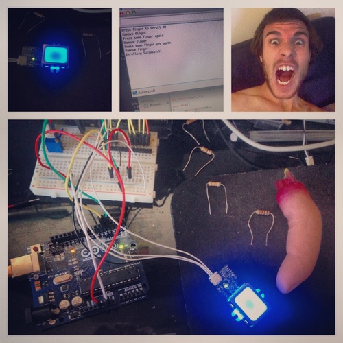
Matt Reamer is a UX designer, graduate student at VCU Brandcenter and a maker. While watching the blockbuster series The Walking Dead , he made up a scene involving a lock-box requiring a finger print to be unlocked. Guess what happens next and who’s the owner of the finger? Watch the video and discover yourself:
He used an Arduino Uno, a servo, a few leds and a Sparkfun FPS scanner.
You can create a customized lock box that recognizes your unique finger print following this documentation on github!
For fun and a little bit of learning, let’s make a Larson Scanner. This isn’t a new project, for example we reviewed a kit in the past – however after finding some large LEDs we decided to make our own version. We’ll use an Arduino-compatible circuit to control the LEDs, and explain both the hardware and required Arduino sketch – then build a temporary small and a more permanent large version (and a bonus project).
So what is a Larson Scanner anyway? Named in honour of Glen A. Larson the creator of television shows such as Battlestar Galactica and Knight Rider – as this kit recreates the left and right blinking motion used in props from those television shows. For example:
Making your own is quite simple, it’s just eight LEDs or lamps blinking in a certain order. If you’re not familiar with the Arduino hardware, please have a quick review of this tutorial before continuing.
Small version
If you’re just interested in whipping up a solderless breadboard or small version, it will take less than fifteen minutes. Just get an Arduino Uno or compatible board and construct the following circuit (the resistors are 560Ω):
The sketch is also very simple. There are two ways to address those digital output pins, and to save sanity and clock cycles we’re going to use port manipulation instead of many digitalWrite() functions. So for our circuit above, enter and upload the following sketch:
// Simple Arduno LED back-and-forth effects, similar to "KITT" from "Knight Rider"
// Original idea by Glen A. Larson
// Arduino sketch - John Boxall 2013

int del=75; // delay between LED movements

void setup()
{
  DDRD = B11111111; // D0~D7 outputs
}

void loop()
{
  PORTD = B00000001;
  delay(del);
  PORTD = B00000011;
  delay(del);
  PORTD = B00000111;
  delay(del);
  PORTD = B00001110;
  delay(del);
  PORTD = B00011100;
  delay(del);
  PORTD = B00111000;
  delay(del);
  PORTD = B01110000;
  delay(del);
  PORTD = B11100000;
  delay(del);
  PORTD = B11000000;
  delay(del);
  PORTD = B10000000;
  delay(del);
  PORTD = B11000000;
  delay(del);
  PORTD = B11100000;
  delay(del);
  PORTD = B01110000;
  delay(del);
  PORTD = B00111000;
  delay(del);
  PORTD = B00011100;
  delay(del);
  PORTD = B00001110;
  delay(del);
  PORTD = B00000111;
  delay(del);
  PORTD = B00000011;
  delay(del);
}
Notice how the ones and zeros in the byte send to PORTD (digital pins 7~0) represent the “movement” of the scanner? You’d have to agree this is a better method of addressing the LEDs. Have some fun and experiment with the patterns you can generate and also the delay. In the following video we’ve quickly demonstrated the circuit on a solderless breadboard using different delay periods:
Large Version
Now to make something more permanent, and much larger. There are many ways of completing this project, so the following version will be a design narrative that you can follow to help with planning your own. The first consideration will be the LEDs you want to use. For our example we used some Kingbright DLC2-6SRD 20mm bright red versions we had in stock:
However you can use what you have available. The key to success will be driving the LEDs at their maximum brightness without damage. So you need to find out the best forward voltage and current for the LEDs, then do some basic mathematics. From our example LEDs’ data sheet, the maximum brightness is from 60 mA of current, at just under 6 V. A quick connection to a variable power supply shows the LEDs at this setting:
We can’t get this kind of brightness from our Arduino 5V circuit, so instead we’ll increase the circuit supply voltage to 9V and use resistors to reduce the current for the LEDs. To find the resistor value, use the following:
… where Vs is the supply voltage (9), VLED is the forward voltage for the LED (5.6), and ILED is the forward current (60 mA). The value for R is 56.66 Ω – however you can’t get that value, so 68 Ω will be the closest value from the supplier. Finally, the power of the resistor required (in watts) is calculated by W = VA. So W = 3.4 (voltage drop over resistor) * 0.06 = 0.204 W. So we’ll need 68 Ω 0.25 W resistors for our LEDs. Thus instead of running the LED straight off a digital output, it will be switched on and off via a simple BC548 transistor – shown in the following schematic example:
The digital output for each LED is connected to the 1k Ω resistor and thus switches the transistor on to allow the current to flow through the LED when required. This is repeated for each LED we intend to use – which for the case of our large scanner project is six. (Why six? Someone bought a board which was too narrow for eight…) Next is the Arduino-compatible circuit. Timing isn’t critical so we’ll save components by using a ceramic resonator instead of a crystal and two capacitors. And as shown below (note that although the image on the microcontroller says ATmega168, we’ll use an ATmega328P):
(If you’re not up for making your own Arduino-compatible circuit, there’s plenty of alternative small boards you can use such as the Nano or LeoStick). Although the symbol for Y1 (the resonator) looks complex, it’s just a resonator – for example:
the centre pin goes to GND and the outside pins go to XTAL1 and XTAL2 on the microcontroller. It isn’t polarised so either direction is fine.
At this point you may also want to consider how you’ll upload and update sketches on the project. One method is to mount the microcontroller in a socket, and just yank it between an Arduino board to upload the sketch, and then put it back in the project board. If you use this method then you’ll need a microcontroller with the Arduino bootloader. However a more civilised method is to add ICSP header pins – they’re the 2 x 3 pins you see on most boards, for example:
With which you can use a USBASP programmer to connect your board directly to a computer just like a normal Arduino. Just use Ctrl-Shift-U to upload your sketch via the programmer. Furthermore you can use bare microcontrollers without the bootloader, as all the necessary code is included with the direct upload. So if this method interests you, add the following to your circuit:
The RESET pin is connected to pin 1 of the microcontroller. Speaking of which, if you’re unsure about which pins on the ATmega328P are which, a variety of suppliers have handy labels you can stick on top, for example:
At this point it’s time to put it all together. We’re using a random piece of prototyping PCB, and your final plan will depend on your board. As an aside, check out the Lochmaster stripboard planning software if you use stripboard a lot. As mentioned earlier your final schematic will vary depending on the number of LEDs, their requirements with respect to current and your choice of Arduino platform. By now you have the knowledge to plan the circuit yourself. After some work here’s our final board:
… and the scanner in action. We used the same sketch as for the temporary version – however reduce it to six outputs (D0~5) to match the LEDs.
Bonus project – Electronic Die
What else can you do with six LEDs? Make an electronic die! Here’s a simple sketch that simply picks a random number every five seconds. The random number generator is seeded from unused an analogue input pin.
// Simple Arduno LED die using Larson Scanner hardware described in http://wp.me/p3LK05-36m
// John Boxall 2013

int del=5000; // delay between new rolls
int num;

byte  digits[] = { B00000001,
                   B00000010,
                   B00000100,
                   B00001000,
                   B00010000,
                   B00100000 };

void setup()
{
  randomSeed(analogRead(0)); // reseed the random number generator with some noise
  DDRD = B11111111; // D0~D7 outputs
}

void rollDie()
{
  for (int i = 0; i< 20; i++)
  {
    num = random(0,6);
    PORTD = digits[num];
    delay(50);
  }
}

void pickNumber()
{
  num = random(0,5);
  PORTD = digits[num];
  delay(1000);
}

void loop()
{
  rollDie();
  pickNumber();
}
And a quick video of our die in action:
Conclusion
We hope you found this interesting and at least made a temporary scanner on a breadboard – or at least learned something. Kudos if you went ahead and made a larger one. If you made a video, share it with us in the comments. And if you made it this far – check out my new book “Arduino Workshop” from No Starch Press.
In the meanwhile have fun and keep checking into tronixstuff.com. Why not follow things on twitter, Google+, subscribe for email updates or RSS using the links on the right-hand column? And join our friendly Google Group – dedicated to the projects and related items on this website. Sign up – it’s free, helpful to each other – and we can all learn something.
Planet Arduino is, or at the moment is wishing to become, an aggregation of public weblogs from around the world written by people who develop, play, think on Arduino platform and his son. The opinions expressed in those weblogs and hence this aggregation are those of the original authors. Entries on this page are owned by their authors. We do not edit, endorse or vouch for the contents of individual posts. For more information about Arduino please visit www.arduino.cc
You are currently browsing the archives for the scanner category.

 Assuming your modern car even has physical buttons, pushing one of them likely sends a message over the CAN bus that the recipient device will (hopefully) respond to. Knowing how intimidating this can be to work with, [TJ Bruno] has been working on some software that promises to make working with CAN bus user interfaces faster and easier. Ultimately, he hopes that his tool will allow users to rapidly integrate custom hardware into their vehicle without having to drill a hole in the dashboard for a physical control.