Posts | Comments

Planet Arduino

Archive for the ‘kit review’ Category

Introduction

From 1981, Australian electrical engineer Colin Mitchell started publishing his home-grown electronics magazine “Talking Electronics”. His goal was to get people interested and learning about electronics, and more so with a focus on digital electronics. It was (and still is) a lofty goal – in which he succeeded. From a couple of rooms in his home the magazine flourished, and many projects described within were sold as kits. At one stage there were over 150 Talking Electronics kits on the market. You could find the books and kits in retail outlets such as Dick Smith Electronics, and for a short while there was a TE store in Moorabbin (Victoria). Colin and the team’s style of writing was easy to read and very understandable – but don’t take my word for it, you can download the magazines from his website (they’re near the bottom of the left column). Dave Jones recently interviewed Colin, and you can watch those for much more background information.

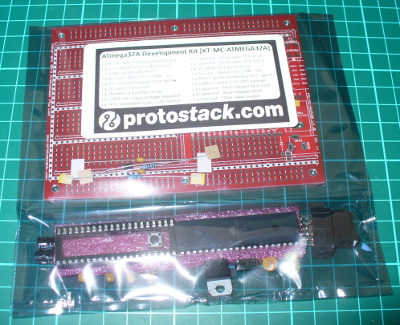
Over fifteen issues you could learn about blinking LEDs all the way to making your own expandable Z80 board computer, and some of the kits may still be available. Colin also published a series of tutorial books on electronics, and also single-magazine projects. And thus the subjects of our review … we came across the first of these single-issue projects from 1981 – the Mini Frequency Counter (then afterwards we have another kit):

cover

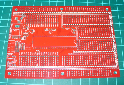
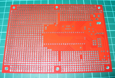
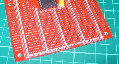
How great is that? The PCB comes with the magazine. This is what set TE apart from the rest, and helped people learn by actually making it easy to build what was described in the magazine instead of just reading about it. For 1981 the PCB was quite good – they were silk-screened which was quite rare at the time:

pcb

pcbrear

And if you weren’t quite ready, the magazine also included details of a square-wave oscillator to make and a 52-page short course in digital electronics. However back to the kit…

Assembly

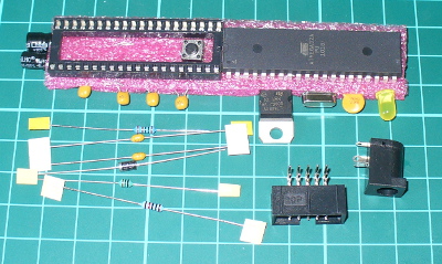
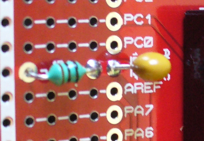
The kit uses common parts and I hoard CMOS ICs so building wasn’t a problem. This (original) version of the kit used LEDs instead of 7-segment displays (which were expensive at the time) so there was plenty of  careful soldering to do:

LEDsin

And after a while the counter started to come together. I used IC sockets just in case:

almostthere

The rest was straight-forward, and before long 9 V was supplied, and we found success:

powerup

To be honest progress floundered for about an hour at this point – the display wouldn’t budge off zero. After checking the multi-vibrator output, calibrating the RC circuits and finally tracing out the circuit with a continuity tester, it turned out one of the links just wasn’t soldered in far enough – and the IC socket for the 4047 was broken So a new link and directly fitting the 4047 fixed it. You live and learn.

Operation

So – we now have a frequency counter that’s good for 100 Hz to the megahertz range, with a minimum of parts. Younger, non-microcontroller people may wonder how that is possible – so here’s the schematic:

schematic

The counter works by using a multi-vibrator using a CD4047 to generate a square-wave at 50, 500 and 5 kHz, and the three trimpots are adjusted to calibrate the output. The incoming pulses to measure are fed to the 4026 decade counter/divider ICs. Three of these operate in tandem and each divide the incoming count by ten – and display or reset by the alternating signal from the 4047. However for larger frequencies (above 900 Hz) you need to change the frequency fed to the display circuit in order to display the higher (left-most) digits of the result. A jumper wire is used to select the required level (however if you mounted the kit in a case, a knob or switch could be used).

For example, if you’re measuring 3.456 MHz you start with the jumper on H and the display reads 345 – then you switch to M to read 456 – then you switch to the L jumper and read 560, giving you 3456000 Hz. If desired, you can extend the kit with another PCB to create a 5-digit display. The counter won’t be winning any precision contests – however it has two purposes, which are fulfilled very well. It gives the reader an inexpensive piece of test equipment that works reasonably well, and a fully-documented project so the reader can understand how it works (and more).

And for the curious –  here it is in action:

[Update 20/07/2013] Siren Kit

Found another kit last week, the Talking Electronics “DIY Kit #31 – 9V siren”. It’s an effective and loud siren with true rise and fall, unlike other kits of the era that alternated between two fixed tones. The packaging was quite strong and idea for mail-order at the time:

kitbox

The label sells the product (and shows the age):

kitlabel

The kit included every part required to work, apart from a PP3 battery, and a single instruction sheet with a good explanation of how the circuit works, and some data about the LM358:

kitparts

… and as usual the PCB was ahead of its’ time with full silk-screen and solder mask:

pcbtop

sirenpcbbottom

Assembly was quite straight-forward. The design is quite compact, so a lot of vertical resistor mounting was necessary due to the lack of space. However it was refreshing to not have any links to fit. After around twenty minutes of relaxed construction, it was ready to test:

PCBfinished

finished

It’s a 1/2 watt speaker, however much louder than originally anticipated:

Once again, another complete and well-produced kit.

Conclusion

That was a lot of fun, and I’m off to make the matching square-wave oscillator for the frequency counter. Kudos to Colin for all those years of publication and helping people learn. Lots of companies bang on about offering tutorials and information on the Internet for free, but Colin has been doing it for over ten years. Check out his Talking Electronics website for a huge variety of knowledge, an excellent electronics course you can get on CD – and go easy on him if you have any questions.

Full-sized images available on flickr. This kit was purchased without notifying the supplier.

And if you made it this far – check out my new book “Arduino Workshop” from No Starch Press.

LEDborder

In the meanwhile have fun and keep checking into tronixstuff.com. Why not follow things on twitterGoogle+, subscribe  for email updates or RSS using the links on the right-hand column? And join our friendly Google Group – dedicated to the projects and related items on this website. Sign up – it’s free, helpful to each other –  and we can all learn something.

The post Australian Electronics Nostalgia – Talking Electronics Kits appeared first on tronixstuff.

Introduction

Every month Australian electronics magazine Silicon Chip publishes a variety of projects, and in March 2004  they published the “DC-DC converter” project. Altronics picked it up and now offers a kit, the subject of our review. The main purpose of this converter kit is to allow replacement of expensive PP3 9V batteries with 2 AA cells, to enable a cheaper and longer lifespan over use. With a slight modification it can also act as a trickle-charger for 2 rechargeable AA cells (that can then supply power to the converter) via a plugpack. And there’s some educational value if you’re so inclined, as you can learn about voltage converters as well.

Assembly

As usual for Altronics the kit is in a typical retail package:

packaged

…which includes the detailed instructions (based on the original Silicon Chip article), a handy reference guide and of course the parts:

contents

The PCB has a good silk screen and solder mask:

pcbtop

pcbbottom

and all the required parts are included:

components

It was nice to see plenty of extra black and red wire for modifications or final installations, the battery snap, 2 x AA cell holder and a DC socket for use with the optional plug pack mentioned earlier. That hand-wound inductor was interesting, and I couldn’t help but measure it on the LC meter:

lcmeter

It was supposed to be a 47 uH inductor, so let’s hope that doesn’t cause too much trouble. Assembly was quite straight-forward – just start with the smallest components first and build up. If you’re not going to have the trickle-charge function, heed the notes in the manual and don’t install D2 or R4. The only fiddly bit was the “short as possible” (red) link across the board:

longlink

And after a few more minutes it was finished. The external connections will vary depending on your application – however for the review I’ve got the 9V snap on the input, which makes it easy to connect the 2 AA cell holder to power the converter. Nice to see the holes around the perimeter of the board, which make mounting it more permanently quite easy.

Operation

After a bench clean-up it was time to connect 2 AA rechargeable cells and see what we can get out of the converter. The cells measured 2.77V together before connection, and without a load on the converter the resulting output was 8.825 V:

firsttest

We can live with that. Furthermore the quiescent current (a situation with the power connected and not having a load on the output) was 2.5 mA. Thus it would be a good idea to have a power switch in a real-world environment. Speaking of the real world (!) how much current can you get out of the converter? Generally PP3 battery applications are low current, as the battery itself isn’t good for that much – even an expensive “Energizer Ultimate Lithium” offers only 800 mAh (for $16). So using higher-capacity rechargeable AA cells and this kit will save money.  A table is included with the instructions that shows the possible uses:

tableofuse

According to the table my 2.77V supply should be good for ~80 mA. With some resistors in parallel we made a dummy load of 69 mA and measured 0.37A current draw from the AA cells. Thus the key to this kit – you find a cheaper or more plentiful power supply at a lower voltage to save you the expense of providing the higher voltage.

For example, if you had a pair of Sanyo Eneloop rechargeable AA cells (total 2.4 V at 2 Ah) they would give you around 5.4 hours of life (ignoring the fall-off of voltage towards the end of their charge life – however the eneloops are pretty good in that regard). Whereas a disposable PP3 mentioned earlier would offer around 2.1 hours (at $16) or a rechargeable unit (which offers 8.4 V at 175 mAh) would only last around 25 minutes. Note that you can change two resistors in the circuit to alter the output voltage, and the values have been listed in the instructions for outputs up to 15 V.

Finally, let’s consider the output waveforms from the circuit. With the aforementioned load, here’s the output on the DSO (click image to enlarge):

output

… and for interest’s sake, the switching output from the TL499 (click images to enlarge):

switchoutput

switchoutputdata

Conclusion

Apart from the described voltage-boosting functions this kit gives the interested builder experience with boost circuits and also the knowledge to create their own versions based on the original design, at a much lower cost than using other boost ICs . If you wanted a permanent certain voltage output, it would be better to breadboard the kit and experiment with the required resistors – then assemble the kit with the new values. And there is money and effort to be saved when subsituting with PP3 batteries. Finally, learning is a good thing!

So – a lot of fun and education for under $20. Purchase it from Altronics and their resellers, or read more about it in the September 2007 edition of Silicon Chip.

Full-sized images available on flickr. This kit was purchased without notifying the supplier.

And if you made it this far – check out my new book “Arduino Workshop” from No Starch Press.

In the meanwhile have fun and keep checking into tronixstuff.com. Why not follow things on twitterGoogle+, subscribe  for email updates or RSS using the links on the right-hand column? And join our friendly Google Group – dedicated to the projects and related items on this website. Sign up – it’s free, helpful to each other –  and we can all learn something.


Introduction

Every month Australian electronics magazine Silicon Chip publishes a variety of projects, and in March 2004  they published the “DC-DC converter” project. Altronics picked it up and now offers a kit, the subject of our review. The main purpose of this converter kit is to allow replacement of expensive PP3 9V batteries with 2 AA cells, to enable a cheaper and longer lifespan over use. With a slight modification it can also act as a trickle-charger for 2 rechargeable AA cells (that can then supply power to the converter) via a plugpack. And there’s some educational value if you’re so inclined, as you can learn about voltage converters as well.

Assembly

As usual for Altronics the kit is in a typical retail package:

packaged

…which includes the detailed instructions (based on the original Silicon Chip article), a handy reference guide and of course the parts:

contents

The PCB has a good silk screen and solder mask:

pcbtop

pcbbottom

and all the required parts are included:

components

It was nice to see plenty of extra black and red wire for modifications or final installations, the battery snap, 2 x AA cell holder and a DC socket for use with the optional plug pack mentioned earlier. That hand-wound inductor was interesting, and I couldn’t help but measure it on the LC meter:

lcmeter

It was supposed to be a 47 uH inductor, so let’s hope that doesn’t cause too much trouble. Assembly was quite straight-forward – just start with the smallest components first and build up. If you’re not going to have the trickle-charge function, heed the notes in the manual and don’t install D2 or R4. The only fiddly bit was the “short as possible” (red) link across the board:

longlink

And after a few more minutes it was finished. The external connections will vary depending on your application – however for the review I’ve got the 9V snap on the input, which makes it easy to connect the 2 AA cell holder to power the converter. Nice to see the holes around the perimeter of the board, which make mounting it more permanently quite easy.

Operation

After a bench clean-up it was time to connect 2 AA rechargeable cells and see what we can get out of the converter. The cells measured 2.77V together before connection, and without a load on the converter the resulting output was 8.825 V:

firsttest

We can live with that. Furthermore the quiescent current (a situation with the power connected and not having a load on the output) was 2.5 mA. Thus it would be a good idea to have a power switch in a real-world environment. Speaking of the real world (!) how much current can you get out of the converter? Generally PP3 battery applications are low current, as the battery itself isn’t good for that much – even an expensive “Energizer Ultimate Lithium” offers only 800 mAh (for $16). So using higher-capacity rechargeable AA cells and this kit will save money.  A table is included with the instructions that shows the possible uses:

tableofuse

According to the table my 2.77V supply should be good for ~80 mA. With some resistors in parallel we made a dummy load of 69 mA and measured 0.37A current draw from the AA cells. Thus the key to this kit – you find a cheaper or more plentiful power supply at a lower voltage to save you the expense of providing the higher voltage.

For example, if you had a pair of Sanyo Eneloop rechargeable AA cells (total 2.4 V at 2 Ah) they would give you around 5.4 hours of life (ignoring the fall-off of voltage towards the end of their charge life – however the eneloops are pretty good in that regard). Whereas a disposable PP3 mentioned earlier would offer around 2.1 hours (at $16) or a rechargeable unit (which offers 8.4 V at 175 mAh) would only last around 25 minutes. Note that you can change two resistors in the circuit to alter the output voltage, and the values have been listed in the instructions for outputs up to 15 V.

Finally, let’s consider the output waveforms from the circuit. With the aforementioned load, here’s the output on the DSO:

output

… and for interest’s sake, the switching output from the TL499:

switchoutput

switchoutputdata

Conclusion

Apart from the described voltage-boosting functions this kit gives the interested builder experience with boost circuits and also the knowledge to create their own versions based on the original design, at a much lower cost than using other boost ICs . If you wanted a permanent certain voltage output, it would be better to breadboard the kit and experiment with the required resistors – then assemble the kit with the new values. And there is money and effort to be saved when subsituting with PP3 batteries. Finally, learning is a good thing!

So – a lot of fun and education for under $20. Purchase it from Altronics and their resellers, or read more about it in the September 2007 edition of Silicon Chip.

Full-sized images available on flickr. This kit was purchased without notifying the supplier.

And if you made it this far – check out my new book “Arduino Workshop” from No Starch Press.

LEDborder

In the meanwhile have fun and keep checking into tronixstuff.com. Why not follow things on twitterGoogle+, subscribe  for email updates or RSS using the links on the right-hand column? And join our friendly Google Group – dedicated to the projects and related items on this website. Sign up – it’s free, helpful to each other –  and we can all learn something.

The post Kit review – Altronics/Silicon Chip DC to DC Converter appeared first on tronixstuff.

Introduction

For those of you prototyping with larger Atmel AVR microcontrollers such as the ATmega32, it can be inconvenient to continually assemble a circuit onto a solderless breadboard that includes power, programming header and a few basics – or you might want to create a one-off product without waiting for a PCB to be made. If these are issues for you, or you’re interested in working with AVRs  then the subject of this review may be of interest – the ATmega32 Development Kit from Protostack. The kit is one of a range that spans from the ATmega8, and gives you almost everything needed to work with the microcontroller. We’ve assembled and experimented with the ATmega32 kit, so read on to find out more.

Assembly

The kit arrives in a typical anti-static package with the contents and URL on the front:

packaging

The PCB is large, measuring 127 x 94 mm, made from heavy 1.6 mm FR4 PCB and all the holes are through-plated. And as you can see from the images below, there’s plenty of prototyping space and power/GND rails:

pcbtop

pcbbottom

The included parts allow you to add a power supply, polyfuse, smoothing capacitors for the power, programmer socket, external 16 MHz crystal, a DC socket, IC socket, a lonely LED and of course the ATmega32A (which is a lower-power version of the ATmega32):

parts

You can download the user guide from the product page, which details the board layout, schematic and so on. When soldering the parts in, just start with the smallest-profile parts first and work your way up. There’s a few clever design points, such as power regulator – there’s four holes so you can use both “in-GND-output” and “GND-output-input” types:

igo

… and the layout of the prototyping areas resemble that of a solderless breadboard, and the power/GND rails snake all around – so transferring projects won’t be difficult at all:

protoarea

If you need to connect the AVcc to Vcc, the components and board space are included for a low-pass filter:

lowpass

And if you get carried away and need to use two or more boards at once – they’re stackable:

stacking

Moving forward

After assembling the board and inserting the ATmega32, you can use an AVR programmer to check it’s all working (and of course program it). With a 10-pin interface USBASP inserted, I headed over to the AVRdude folder on my PC and entered:

avrdude -c usbasp -p m32

which (as all was well) resulted with:

avrdudetest

Awesome – it’s nice to have something that just works. Let the experimenting begin!

Competition

Would you like the chance to win a kit? It’s easy. Clearly print your email address on a postcard, and mail it to:

Protostack Competition, PO Box 5435, Clayton 3168, Australia

Entries must be received by the 4th of  August 2013. One postcard will then be drawn at random, and the winner will receive one ATmega32 kit delivered by Australia Post standard air mail. You can enter as many times as you like. We’re not responsible for customs or import duties, VAT, GST, postage delays, non-delivery or whatever walls your country puts up against receiving inbound mail.

Conclusion

It’s a solid kit, the PCB is solid as a rock, and it worked. However it could really have used some spacers or small rubber feet to keep the board off the bench. Otherwise the kit is excellent, and offers a great prototyping area to work with your projects. If you order some, Protostack have a maximum delivery charge of $9 so you won’t get burned on delivery to far-flung places.  Larger photos available on flickr. And if you made it this far – check out my new book “Arduino Workshop” from No Starch Press.

Please note that the ATMEGA32A Development Kit in this review is a promotional consideration from Protostack.

In the meanwhile have fun and keep checking into tronixstuff.com. Why not follow things on twitterGoogle+, subscribe  for email updates or RSS using the links on the right-hand column? And join our friendly Google Group – dedicated to the projects and related items on this website. Sign up – it’s free, helpful to each other –  and we can all learn something.


Introduction

For those of you prototyping with larger Atmel AVR microcontrollers such as the ATmega32, it can be inconvenient to continually assemble a circuit onto a solderless breadboard that includes power, programming header and a few basics – or you might want to create a one-off product without waiting for a PCB to be made. If these are issues for you, or you’re interested in working with AVRs  then the subject of this review may be of interest – the ATmega32 Development Kit from Protostack. The kit is one of a range that spans from the ATmega8, and gives you almost everything needed to work with the microcontroller. We’ve assembled and experimented with the ATmega32 kit, so read on to find out more.

Assembly

The kit arrives in a typical anti-static package with the contents and URL on the front:

packaging

The PCB is large, measuring 127 x 94 mm, made from heavy 1.6 mm FR4 PCB and all the holes are through-plated. And as you can see from the images below, there’s plenty of prototyping space and power/GND rails:

pcbtop

pcbbottom

The included parts allow you to add a power supply, polyfuse, smoothing capacitors for the power, programmer socket, external 16 MHz crystal, a DC socket, IC socket, a lonely LED and of course the ATmega32A (which is a lower-power version of the ATmega32):

parts

You can download the user guide from the product page, which details the board layout, schematic and so on. When soldering the parts in, just start with the smallest-profile parts first and work your way up. There’s a few clever design points, such as power regulator – there’s four holes so you can use both “in-GND-output” and “GND-output-input” types:

igo

… and the layout of the prototyping areas resemble that of a solderless breadboard, and the power/GND rails snake all around – so transferring projects won’t be difficult at all:

protoarea

If you need to connect the AVcc to Vcc, the components and board space are included for a low-pass filter:

lowpass

And if you get carried away and need to use two or more boards at once – they’re stackable:

stacking

Moving forward

After assembling the board and inserting the ATmega32, you can use an AVR programmer to check it’s all working (and of course program it). With a 10-pin interface USBASP inserted, I headed over to the AVRdude folder on my PC and entered:

avrdude -c usbasp -p m32

which (as all was well) resulted with:

avrdudetest2

Awesome – it’s nice to have something that just works. Let the experimenting begin!

Conclusion

It’s a solid kit, the PCB is solid as a rock, and it worked. However it could really have used some spacers or small rubber feet to keep the board off the bench. Otherwise the kit is excellent, and offers a great prototyping area to work with your projects. If you order some, Protostack have a maximum delivery charge of $9 so you won’t get burned on delivery to far-flung places.  Larger photos available on flickr. And if you made it this far – check out my new book “Arduino Workshop” from No Starch Press.

LEDborder

Please note that the ATMEGA32A Development Kit in this review is a promotional consideration from Protostack.

In the meanwhile have fun and keep checking into tronixstuff.com. Why not follow things on twitterGoogle+, subscribe  for email updates or RSS using the links on the right-hand column? And join our friendly Google Group – dedicated to the projects and related items on this website. Sign up – it’s free, helpful to each other –  and we can all learn something.

The post Kit review – Protostack ATmega32 Development Kit appeared first on tronixstuff.

Jun
11

Kit review – the Freetronics CUBE4: RGB LED Cube

4x4x4, arduino, argot, cube, freetronics, jaycar, kit, kit review, LED, leonardo, LeoStick, review, RGB, XC4274 Comments Off on Kit review – the Freetronics CUBE4: RGB LED Cube 

Introduction

LED cubes are a fascinating item, no matter where you come from the allure of blinking LEDs in various patterns is always attractive. And making your own is a fun challenge that most people can do after some experience with electronics hardware. However most people use single-colour LEDs, as wiring up RGB units triples the complexity of the circuit. Until now.

After much anticipation Freetronics have released their CUBE4 RGB LED cube kit – a simple to assemble and completely-customisable RGB LED cube:

cube4off

Unlike other cubes on the market, this one includes an on-board ATmega32u4 microcontroller with Arduino Leonardo-compatible bootloader and a microUSB socket (… and a lot more) – so you don’t need anything extra to get started. And this gives you many more options when you’re ready to expand. But first let’s put it together and then get it working. Furthermore, keep reading to find out how you can have a chance to win your own Cube4.

Assembly

Inside the box are all the parts needed for the kit, even a microUSB cable to power the Cube4 and also communicate with it:

parts

There’s 64 RGB LEDs in that bag, so get ready for some soldering. The base PCB is well laid out, labelled and gives you an idea for the expansion possibilities:

PCBtop

Plenty of room to add your own circuitry – and the bottom:

PCBbottom

As you can see in the image above, there’s an XBee-compatible pinout if you want to add communication via wirless serial link, plenty of prototyping space for your own additions and many other ports are brought out to open pads. There’s even a 5V supply pair to test LEDs, and a blue “power on” LED (which can be deactivated if necessary by cutting a track on the PCB).

The first job is to mount the LEDs on their plane PCBs – there are four, one for each horizontal plant. It’s very important to get the LEDs in the right way round, and there’s markers on the PCB that you can match up the longest leg of the LED with:

LEDinsertdirection

From experience I found it best to insert all the LEDs:

LEDsinserted

…and then do a final mass check of the alignment – which is easy if you hold the plane up to one side and compare the legs, for example:

checkLEDdirection

At this stage it’s a great idea to double-check your LED alignment. After a while you’ll have the LEDs soldered in and trimmed nicely:

LEDssoldered

The next step was getting the vertical sticks aligned in order to hold the LED planes (above). Each stick is for a particular spot on the PCB so check the label on the stick matches the hole on the PCB. It’s incredibly important to make sure you have them perfectly perpendicular to the PCB, so find something like a square-edge or card to help out:

alignstick

Once you have a row of sticks in you can start with a plane then insert a stick on the other side, for example:

firstplanerubberband

Note the use of the elastic band to hold things together – they really help. Then it’s a simple matter of adding the planes and holding it together with another band:

fourplanespresolder

… at which point you can do a final check that all the planes and sticks are inserted correctly. Then solder all the copper spots together and you’re done.

Don’t forget to turn the cube upside-down as there’s soldering to be done on the bottom of the planes as well:

solderupsidedownaswell

 Although it might look a little scary, the final assembly isn’t that difficult – just take your time so it’s right the first time. You can view the following video which describes the entire process:

Once you’re confident that all the soldering has been completed – double-check for joints that aren’t completely bridged with solder as they will affect the operation of the cube. Then you can plug in the USB cable and watch the preloaded test/demonstration sketch in action:

If all your LEDs are working, awesome. If not – check the soldering. If there’s still some rogues – check your individual LEDs. Some of you are probably thinking “well that isn’t too colourful” – the problem is the camera, not the Cube4. If you see it in real life, it’s much better.

Operation

There are two methods of controlling the Cube4. It is delivered with a preloaded sketch that runs the demonstration showed in the video above, and then accepts commands over a serial/USB connection. So you can simply plug it in, fire up a terminal program (or the Arduino IDE serial monitor) and send text commands to do various things. If you type “help ;” the syntax is returned which explains how you can do things:

helpscreen

This serial control mode allows control by any type of software that can write to a serial port. Furthermore any other external hardware that can create or introduce serial text can also control the Cube4. For example by mounting an XBee module underneath and linking it to the TX/RX lines gives you a wireless Cube4. By doing so you can control it with a Raspberry Pi or other system.

Furthermore the Cube4 is also an Arduino Leonardo-compatible board in the same way as a Freetronics LeoStick.  With the use of the Cube4 Arduino library you can then create your own sketches which can visualise data with very simple to use functions for the Cube4. There are some great example sketches with the library for some inspiration and fun. Over time I look forward to using the Cube4 in various ways, including adding an Electric Imp IoT device and making another clock (!).

More demonstrations

Check out this Argot IoT demonstration.

Conclusion

This is the most approachable RGB LED cube kit on the market, and also the easiest to use. You don’t need to understand programming to try it out – and if you do it’s incredibly versatile. A lot of work has gone into the library, API and hardware design so you’ve got an expandable tool and not just some blinking LEDs. For more information visit the Freetronics website.  Larger photos available on flickr. And if you made it this far – check out my new book “Arduino Workshop” from No Starch Press.

LEDborder

The CUBE4 in this review is a promotional consideration from Freetronics. In the meanwhile have fun and keep checking into tronixstuff.com. Why not follow things on twitterGoogle+, subscribe  for email updates or RSS using the links on the right-hand column? And join our friendly Google Group – dedicated to the projects and related items on this website. Sign up – it’s free, helpful to each other –  and we can all learn something.

The post Kit review – the Freetronics CUBE4: RGB LED Cube appeared first on tronixstuff.

Jun
11

Kit review – the Freetronics CUBE4: RGB LED Cube

4x4x4, arduino, argot, cube, freetronics, jaycar, kit, kit review, LED, leonardo, LeoStick, review, RGB, XC4274 Comments Off on Kit review – the Freetronics CUBE4: RGB LED Cube 

Introduction

LED cubes are a fascinating item, no matter where you come from the allure of blinking LEDs in various patterns is always attractive. And making your own is a fun challenge that most people can do after some experience with electronics hardware. However most people use single-colour LEDs, as wiring up RGB units triples the complexity of the circuit. Until now.

After much anticipation Freetronics have released their CUBE4 RGB LED cube kit – a simple to assemble and completely-customisable RGB LED cube:

cube4off

Unlike other cubes on the market, this one includes an on-board ATmega32u4 microcontroller with Arduino Leonardo-compatible bootloader and a microUSB socket (… and a lot more) – so you don’t need anything extra to get started. And this gives you many more options when you’re ready to expand. But first let’s put it together and then get it working. Furthermore, keep reading to find out how you can have a chance to win your own Cube4.

Assembly

Inside the box are all the parts needed for the kit, even a microUSB cable to power the Cube4 and also communicate with it:

parts

There’s 64 RGB LEDs in that bag, so get ready for some soldering. The base PCB is well laid out, labelled and gives you an idea for the expansion possibilities:

PCBtop

Plenty of room to add your own circuitry – and the bottom:

PCBbottom

As you can see in the image above, there’s an XBee-compatible pinout if you want to add communication via wirless serial link, plenty of prototyping space for your own additions and many other ports are brought out to open pads. There’s even a 5V supply pair to test LEDs, and a blue “power on” LED (which can be deactivated if necessary by cutting a track on the PCB).

The first job is to mount the LEDs on their plane PCBs – there are four, one for each horizontal plant. It’s very important to get the LEDs in the right way round, and there’s markers on the PCB that you can match up the longest leg of the LED with:

LEDinsertdirection

From experience I found it best to insert all the LEDs:

LEDsinserted

…and then do a final mass check of the alignment – which is easy if you hold the plane up to one side and compare the legs, for example:

checkLEDdirection

At this stage it’s a great idea to double-check your LED alignment. After a while you’ll have the LEDs soldered in and trimmed nicely:

LEDssoldered

The next step was getting the vertical sticks aligned in order to hold the LED planes (above). Each stick is for a particular spot on the PCB so check the label on the stick matches the hole on the PCB. It’s incredibly important to make sure you have them perfectly perpendicular to the PCB, so find something like a square-edge or card to help out:

alignstick

Once you have a row of sticks in you can start with a plane then insert a stick on the other side, for example:

firstplanerubberband

Note the use of the elastic band to hold things together – they really help. Then it’s a simple matter of adding the planes and holding it together with another band:

fourplanespresolder

… at which point you can do a final check that all the planes and sticks are inserted correctly. Then solder all the copper spots together and you’re done.

Don’t forget to turn the cube upside-down as there’s soldering to be done on the bottom of the planes as well:

solderupsidedownaswell

 Although it might look a little scary, the final assembly isn’t that difficult – just take your time so it’s right the first time. You can view the following video which describes the entire process:

Once you’re confident that all the soldering has been completed – double-check for joints that aren’t completely bridged with solder as they will affect the operation of the cube. Then you can plug in the USB cable and watch the preloaded test/demonstration sketch in action:

If all your LEDs are working, awesome. If not – check the soldering. If there’s still some rogues – check your individual LEDs. Some of you are probably thinking “well that isn’t too colourful” – the problem is the camera, not the Cube4. If you see it in real life, it’s much better.

Operation

There are two methods of controlling the Cube4. It is delivered with a preloaded sketch that runs the demonstration showed in the video above, and then accepts commands over a serial/USB connection. So you can simply plug it in, fire up a terminal program (or the Arduino IDE serial monitor) and send text commands to do various things. If you type “help ;” the syntax is returned which explains how you can do things (click image to enlarge):

helpscreen

This serial control mode allows control by any type of software that can write to a serial port. Furthermore any other external hardware that can create or introduce serial text can also control the Cube4. For example by mounting an XBee module underneath and linking it to the TX/RX lines gives you a wireless Cube4. By doing so you can control it with a Raspberry Pi or other system.

Furthermore the Cube4 is also an Arduino Leonardo-compatible board in the same way as a Freetronics LeoStick.  With the use of the Cube4 Arduino library you can then create your own sketches which can visualise data with very simple to use functions for the Cube4. There are some great example sketches with the library for some inspiration and fun. Over time I look forward to using the Cube4 in various ways, including adding an Electric Imp IoT device and making another clock (!).

Competition

Would you like the chance to win a Cube4? It’s easy. Clearly print your email address on a postcard, and mail it to:

CUBE4 Competition, PO Box 5435, Clayton 3168, Australia

Entries must be received by the 30th of  July 2013. One postcard will then be drawn at random, and the winner will receive one Cube4 delivered by Australia Post standard air mail. You can enter as many times as you like. We’re not responsible for customs or import duties, VAT, GST, postage delays, non-delivery or whatever walls your country puts up against receiving inbound mail.

More demonstrations

Check out this Argot IoT demonstration.

Conclusion

This is the most approachable RGB LED cube kit on the market, and also the easiest to use. You don’t need to understand programming to try it out – and if you do it’s incredibly versatile. A lot of work has gone into the library, API and hardware design so you’ve got an expandable tool and not just some blinking LEDs. For more information visit the Freetronics website.  Larger photos available on flickr. And if you made it this far – check out my new book “Arduino Workshop” from No Starch Press.

The CUBE4 in this review is a promotional consideration from Freetronics. In the meanwhile have fun and keep checking into tronixstuff.com. Why not follow things on twitterGoogle+, subscribe  for email updates or RSS using the links on the right-hand column? And join our friendly Google Group – dedicated to the projects and related items on this website. Sign up – it’s free, helpful to each other –  and we can all learn something.


Jun
03

Introduction

Every month Australian electronics magazine Silicon Chip publishes a few projects, and in this quick kit review we’ll look at an older but still current example from September 2007 – the 3-state PIC Logic Probe Kit. This is an inexpensive piece of test equipment that’s useful when checking digital logic states and as a kit, a challenging hand-soldering effort.

Assembly

The kit is packaged in typical form, without any surprises:

kitpack

As mentioned earlier this kit is an interesting challenge due to the size of the PCB and the use of surface-mount components. The designer’s goal was to have the entire unit fit inside a biro housing (without the ink!). Thus the entire thing is using SMT parts.

Thankfully the LEDs are packaged individually into labelled bags, as alone they’re identical to the naked eye. Although the kit wasn’t expensive, it would have been nice for one extra component of each type – beginners tend to lose the tiny parts. The cost could perhaps be offset by not including the usual solder which is too thick for use with the kit.

parts

Nevertheless with some care assembly can begin. After cleaning the PCB with some aerosol cleaner, it was tacked it to the desk mat to make life a little easier:

pcb

If you want one of those rulers – click here. Before building the kit it occurred to me that the normal soldering iron tip would be too large, so I ordered a tiny 0.2mm conical tip for the Hakko:

newtip

The tip on your average iron may be too large, so take this into account when trying to hand solder SMT components. The instructions include a guide on SMT hand-soldering for the uninitiated, well worth reading before starting.

Moving forward, soldering the parts was a slow and patient process. (With hindsight one could use the reflow soldering method to take care of the SMT and then carefully fit the links to the PCB). The instructions are quite good and include a short “how to solder SMT” guide, a PCB layout plan:

instructions

… along with an guide that helps identity the components:

instructionssmt

When soldering, make sure you have the time and patience not to rush the job. And don’t sneeze – after doing so I lost the PIC microcontroller for a few moments trying to find where it landed. Once the LEDs have been soldered in and their current-limiting resistors, it’s a good time to quickly test them by applying 5V and GND. I used the diode test feature of the multimeter which generates enough current to light them up.

Due to the PCB being single-sided (!) you also need to solder in some links. It’s best to do these before the button (and before soldering any other parts near the link holes), and run the wires beneath the top surface, for example:

links

… and after doing so, you’ll need more blu-tack to hold it down!

gettingthere

One of the trickiest parts of this kit was soldering the sewing needle at the end of the PCB to act as the probe tip – as you can see in the photo below, solder doesn’t take to them that well – however after a fair amount it does the job:

needle

At this point it’s recommended you solder the wires to the PCB (for power) and then insert the probe into the pen casing. For the life of me I didn’t have a spare pen around here so instead we’re going to cover it in clear heatshrink. Thus leaving the final task as soldering the alligator clips to the power wires:

finished

Operation

What is a logic probe anyway? It shows what the logic level is at the probed point in a circuit. To do this you connect the black and red alligator clips to 0V and a supply voltage up to 18V respectively – then poke the probe tip at the point where you’re curious about the voltage levels. If it’s at a “high” state (on, or “1″ or whatever you want to call it) the red LED comes on.

If it’s “low” the green LED comes on. The third (orange) LED has two modes. It can either pulse every 50 mS when the logic state changes – or in “latch mode” it will come on and stay on when the mode changes, ideal for detecting infrequent changes in the logic state of the test point.

The kit uses a Microchip PIC12F20x microcontroller, and also includes the hardware schematic to make a basic RS232 PIC programmer and wiring instructions for reprogramming it if you want to change the code or operation of the probe.

Conclusion

The PIC Logic Probe is a useful piece of equipment if you want a very cheap way to monitor logic levels. It wasn’t the easiest kit to solder, and if Altronics revised it so the PCB was double-sided and changed the parts layout, there would be more space to solder some parts and thus make the whole thing a lot easier.

Nevertheless for under $17 it’s worth it. You can purchase it from Altronics and their resellers, or read more about it in the September 2007 edition of Silicon Chip. Full-sized images available on flickr. This kit was purchased without notifying the supplier. And if you made it this far – check out my new book “Arduino Workshop” from No Starch Press.

LEDborder

In the meanwhile have fun and keep checking into tronixstuff.com. Why not follow things on twitterGoogle+, subscribe  for email updates or RSS using the links on the right-hand column? And join our friendly Google Group – dedicated to the projects and related items on this website. Sign up – it’s free, helpful to each other –  and we can all learn something.

The post Kit review – Altronics/SC PIC Logic Probe Kit appeared first on tronixstuff.

Jun
03

Kit review – Altronics/SC PIC Logic Probe Kit

altronics, chip, K2587, kit, kit review, logic, pic, probe, review, silicon, SMT, soldering, test equipment, tronixstuff Comments Off on Kit review – Altronics/SC PIC Logic Probe Kit 

Introduction

Every month Australian electronics magazine Silicon Chip publishes a few projects, and in this quick kit review we’ll look at an older but still current example from September 2007 – the 3-state PIC Logic Probe Kit. This is an inexpensive piece of test equipment that’s useful when checking digital logic states and as a kit, a challenging hand-soldering effort.

Assembly

The kit is packaged in typical form, without any surprises:

kitpack

As mentioned earlier this kit is an interesting challenge due to the size of the PCB and the use of surface-mount components. The designer’s goal was to have the entire unit fit inside a biro housing (without the ink!). Thus the entire thing is using SMT parts.

Thankfully the LEDs are packaged individually into labelled bags, as alone they’re identical to the naked eye. Although the kit wasn’t expensive, it would have been nice for one extra component of each type – beginners tend to lose the tiny parts. The cost could perhaps be offset by not including the usual solder which is too thick for use with the kit.

parts

Nevertheless with some care assembly can begin. After cleaning the PCB with some aerosol cleaner, it was tacked it to the desk mat to make life a little easier:

pcb

If you want one of those rulers – click here. Before building the kit it occurred to me that the normal soldering iron tip would be too large, so I ordered a tiny 0.2mm conical tip for the Hakko:

newtip

The tip on your average iron may be too large, so take this into account when trying to hand solder SMT components. The instructions include a guide on SMT hand-soldering for the uninitiated, well worth reading before starting.

Moving forward, soldering the parts was a slow and patient process. (With hindsight one could use the reflow soldering method to take care of the SMT and then carefully fit the links to the PCB). The instructions are quite good and include a short “how to solder SMT” guide, a PCB layout plan:

instructions

… along with an guide that helps identity the components:

instructionssmt

When soldering, make sure you have the time and patience not to rush the job. And don’t sneeze – after doing so I lost the PIC microcontroller for a few moments trying to find where it landed. Once the LEDs have been soldered in and their current-limiting resistors, it’s a good time to quickly test them by applying 5V and GND. I used the diode test feature of the multimeter which generates enough current to light them up.

Due to the PCB being single-sided (!) you also need to solder in some links. It’s best to do these before the button (and before soldering any other parts near the link holes), and run the wires beneath the top surface, for example:

links

… and after doing so, you’ll need more blu-tack to hold it down!

gettingthere

One of the trickiest parts of this kit was soldering the sewing needle at the end of the PCB to act as the probe tip – as you can see in the photo below, solder doesn’t take to them that well – however after a fair amount it does the job:

needle

At this point it’s recommended you solder the wires to the PCB (for power) and then insert the probe into the pen casing. For the life of me I didn’t have a spare pen around here so instead we’re going to cover it in clear heatshrink. Thus leaving the final task as soldering the alligator clips to the power wires:

finished

Operation

What is a logic probe anyway? It shows what the logic level is at the probed point in a circuit. To do this you connect the black and red alligator clips to 0V and a supply voltage up to 18V respectively – then poke the probe tip at the point where you’re curious about the voltage levels. If it’s at a “high” state (on, or “1″ or whatever you want to call it) the red LED comes on.

If it’s “low” the green LED comes on. The third (orange) LED has two modes. It can either pulse every 50 mS when the logic state changes – or in “latch mode” it will come on and stay on when the mode changes, ideal for detecting infrequent changes in the logic state of the test point.

The kit uses a Microchip PIC12F20x microcontroller, and also includes the hardware schematic to make a basic RS232 PIC programmer and wiring instructions for reprogramming it if you want to change the code or operation of the probe.

Conclusion

The PIC Logic Probe is a useful piece of equipment if you want a very cheap way to monitor logic levels. It wasn’t the easiest kit to solder, and if Altronics revised it so the PCB was double-sided and changed the parts layout, there would be more space to solder some parts and thus make the whole thing a lot easier.

Nevertheless for under $17 it’s worth it. You can purchase it from Altronics and their resellers, or read more about it in the September 2007 edition of Silicon Chip. Full-sized images available on flickr. This kit was purchased without notifying the supplier. And if you made it this far – check out my new book “Arduino Workshop” from No Starch Press.

In the meanwhile have fun and keep checking into tronixstuff.com. Why not follow things on twitterGoogle+, subscribe  for email updates or RSS using the links on the right-hand column? And join our friendly Google Group – dedicated to the projects and related items on this website. Sign up – it’s free, helpful to each other –  and we can all learn something.


Introduction

Every month Australian electronics magazine Silicon Chip publishes a variety of projects, and in January 2013 they published the “Garbage Recycling Reminder” by John Clarke. Jaycar picked it up and now offers a kit, the subject of our review. This kit solves the old but recurring (for some) problem – which bin to put out, and when!

The kit offers a simple way of keeping track of the bin schedule, and is suitable for up to four bins. With a simple user-interface consisting of a button and LED for each bin – once setup the reminder can easily be used by anyone. It allows for weekly, fortnightly and alternate fortnights – which is perfect for almost every council’s schedule.

Assembly

The kit arrives in typical Jaycar fashion:

and includes everything you need, including an enclosure, front panel sticker and battery:

 The PCB is well done, and routed nicely to fit inside the enclosure:

Now to get started. The instructions included are a reprint of the magazine article, and as Jaycar have modified the kit a little, their notes and photos are also included. However there isn’t anything to worry about.

Assembly is straight-forward, the only annoying thing was the assumption that the constructor will use off-cuts for jumper links. Instead – use your own header pins:

Furthermore, when soldering in the resistors and 1N914 diodes next to the LEDs – leave them floating so you can move them a bit to make way for the LEDs:

This is also a good time to check the buttons line up with the holes drilled into the front panel (a template is included with the instructions):

At this point you can fit the LEDs to the PCB, and carefully match it up with the drilled lid. You are supplied with a red, green, yellow and blue LED – which generally match the bin lid colours from various councils. Screw the PCB into the lid then solder the LEDs in – after double-checking they protrude out of lid. Then insert the battery and make a final test:

If you made it that far, you can apply the sticker included to illustrate the front panel. To save time we cut the sticker up for a minimalist look. However you now need to set-up the jumpers before closing the box up. There is a set of three pins for each bin, and a jumper can bridge the first two or last two pins, or none. If you don’t bridge them – that bin is weekly. If you bridge the first two – that bin is fortnightly from the setup day. If you bridge the last two – that bin is fortnightly from the next week, for example:

So you can easily set it up for a weekly bin and an alternating-fortnight pair of bins. Once you’ve setup the jumpers, screw up the box and you’re done.

Operation

Once you’ve set the jumpers up as described earlier, you just need to execute the programming function at the time you want the reminders to start every week. For example, if your weekly collection is 4 AM on a Thursday – do the programming around 5pm Wednesday night – that will then be the time the LEDs start blinking. When you put out the appropriate bin, press the button below the matching bin LED to stop the blinking. You can control the number of bins – so if you only have two bins, only two LEDs will activate. The blinking period is eighteen hours, and you can adjust the start time via the buttons.

How it works

The circuit is based around a Microchip PIC16LF88 and has an incredibly low current draw, around 15 uA when the LEDs aren’t blinking. This allows the circuit to run for over two years on the included 3v coin cell battery. The internal clock is kept accurate to around 10 minutes per year using an external 32.768 kHz crystal. After a period of use the battery voltage may drop to a level insufficient to adequately power the LEDs, so each one has a voltage doubler by way of a diode and capacitor – very clever. This ensures LED brightness even with a low battery. For complete details purchase the kit or a copy of the January 2013 edition of Silicon Chip.

Now it sits next to the kettle, waiting for bin night…

Conclusion

Personally I needed this kit, so I’m a little biased towards it. However – it’s simple and it works. Kudos to John Clarke for his project. You can purchase it from Jaycar and their resellers, or read more about it in the January 2013 edition of Silicon Chip. Full-sized images available on flickr. This kit was purchased without notifying the supplier.

In the meanwhile have fun and keep checking into tronixstuff.com. Why not follow things on twitterGoogle+, subscribe  for email updates or RSS using the links on the right-hand column? And join our friendly Google Group – dedicated to the projects and related items on this website. Sign up – it’s free, helpful to each other –  and we can all learn something.

The post Kit Review – SC/Jaycar Garbage and Recycling Reminder appeared first on tronixstuff.


  • Newsletter

    Sign up for the PlanetArduino Newsletter, which delivers the most popular articles via e-mail to your inbox every week. Just fill in the information below and submit.

  • Like Us on Facebook