
12
Kit Review – SC/Jaycar Garbage and Recycling Reminder
Electronics, garbage, jaycar, KC5518, kit review, pic, PIC16LF88, recycling, reminder, silicon chip, tronixstuff, tutorial Comments Off on Kit Review – SC/Jaycar Garbage and Recycling Reminder
Introduction
Every month Australian electronics magazine Silicon Chip publishes a variety of projects, and in January 2013 they published the “Garbage Recycling Reminder” by John Clarke. Jaycar picked it up and now offers a kit, the subject of our review. This kit solves the old but recurring (for some) problem – which bin to put out, and when!

The kit offers a simple way of keeping track of the bin schedule, and is suitable for up to four bins. With a simple user-interface consisting of a button and LED for each bin – once setup the reminder can easily be used by anyone. It allows for weekly, fortnightly and alternate fortnights – which is perfect for almost every council’s schedule.
Assembly
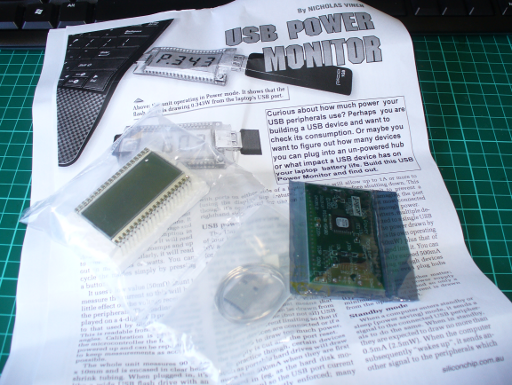
The kit arrives in typical Jaycar fashion:

and includes everything you need, including an enclosure, front panel sticker and battery:

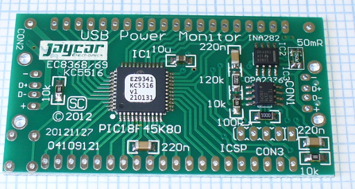
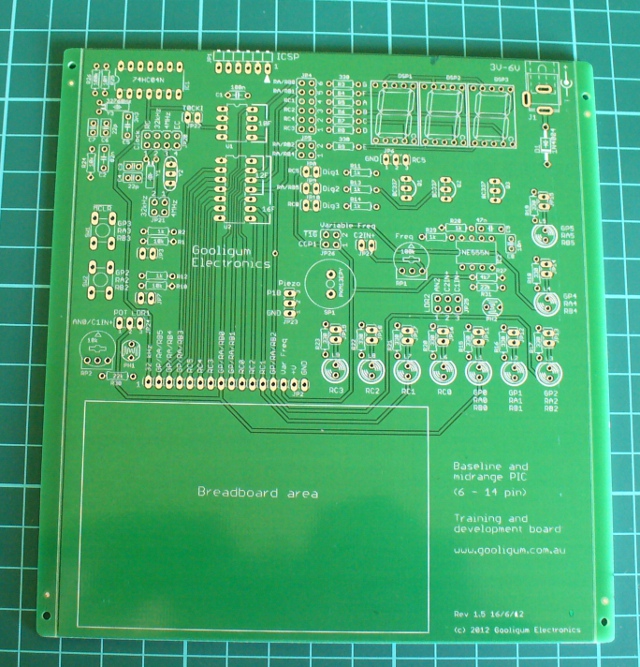
The PCB is well done, and routed nicely to fit inside the enclosure:


Now to get started. The instructions included are a reprint of the magazine article, and as Jaycar have modified the kit a little, their notes and photos are also included. However there isn’t anything to worry about.

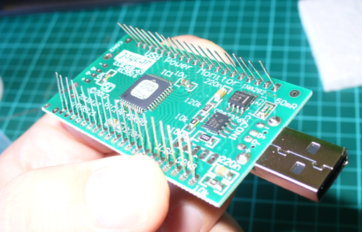
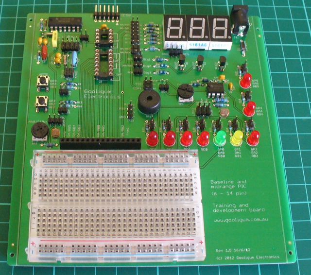
Assembly is straight-forward, the only annoying thing was the assumption that the constructor will use off-cuts for jumper links. Instead – use your own header pins:

Furthermore, when soldering in the resistors and 1N914 diodes next to the LEDs – leave them floating so you can move them a bit to make way for the LEDs:

This is also a good time to check the buttons line up with the holes drilled into the front panel (a template is included with the instructions):

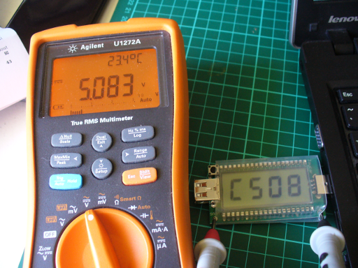
At this point you can fit the LEDs to the PCB, and carefully match it up with the drilled lid. You are supplied with a red, green, yellow and blue LED – which generally match the bin lid colours from various councils. Screw the PCB into the lid then solder the LEDs in – after double-checking they protrude out of lid. Then insert the battery and make a final test:
If you made it that far, you can apply the sticker included to illustrate the front panel. To save time we cut the sticker up for a minimalist look. However you now need to set-up the jumpers before closing the box up. There is a set of three pins for each bin, and a jumper can bridge the first two or last two pins, or none. If you don’t bridge them – that bin is weekly. If you bridge the first two – that bin is fortnightly from the setup day. If you bridge the last two – that bin is fortnightly from the next week, for example:

So you can easily set it up for a weekly bin and an alternating-fortnight pair of bins. Once you’ve setup the jumpers, screw up the box and you’re done.
Operation
Once you’ve set the jumpers up as described earlier, you just need to execute the programming function at the time you want the reminders to start every week. For example, if your weekly collection is 4 AM on a Thursday – do the programming around 5pm Wednesday night – that will then be the time the LEDs start blinking. When you put out the appropriate bin, press the button below the matching bin LED to stop the blinking. You can control the number of bins – so if you only have two bins, only two LEDs will activate. The blinking period is eighteen hours, and you can adjust the start time via the buttons.
How it works
The circuit is based around a Microchip PIC16LF88 and has an incredibly low current draw, around 15 uA when the LEDs aren’t blinking. This allows the circuit to run for over two years on the included 3v coin cell battery. The internal clock is kept accurate to around 10 minutes per year using an external 32.768 kHz crystal. After a period of use the battery voltage may drop to a level insufficient to adequately power the LEDs, so each one has a voltage doubler by way of a diode and capacitor – very clever. This ensures LED brightness even with a low battery. For complete details purchase the kit or a copy of the January 2013 edition of Silicon Chip.

Now it sits next to the kettle, waiting for bin night…
Conclusion
Personally I needed this kit, so I’m a little biased towards it. However – it’s simple and it works. Kudos to John Clarke for his project. You can purchase it from Jaycar and their resellers, or read more about it in the January 2013 edition of Silicon Chip. Full-sized images available on flickr. This kit was purchased without notifying the supplier.

In the meanwhile have fun and keep checking into tronixstuff.com. Why not follow things on twitter, Google+, subscribe for email updates or RSS using the links on the right-hand column? And join our friendly Google Group – dedicated to the projects and related items on this website. Sign up – it’s free, helpful to each other – and we can all learn something.


