Posts | Comments

Planet Arduino

Archive for the ‘microcontrollers’ Category

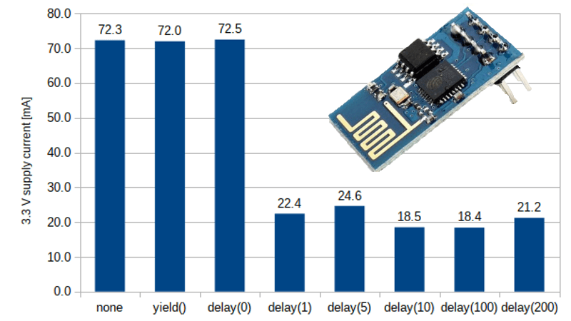
Arduino has a library for quickly and easily setting up a simple web server on an ESP8622-based board, and [Tomaž] found that power consumption on an ESP-01 can be reduced a considerable amount by simply inserting a 1 ms delay in the right place. The reason this works isn’t because of some strange bug or oddball feature — it’s really just a side effect of how the hardware operates under the hood.

[Tomaž] uses the “hello world” example from ESP8266WebServer to explain. In it, the main loop essentially consists of calling server.handleClient() forever. That process checks for incoming HTTP connections, handles them, sends responses, exits — and then does it all over again. A simple web server like this one spends most of its time waiting.

A far more efficient way to handle things would be to launch server.handleClient() only when an incoming network connection calls for it, and put the hardware to sleep whenever that is not happening. However, that level of control just isn’t possible in the context of the Arduino’s ESP8266WebServer library.

So what’s to be done? The next best thing turns out to be a simple delay(1) statement right after each server.handleClient() call in the main loop.

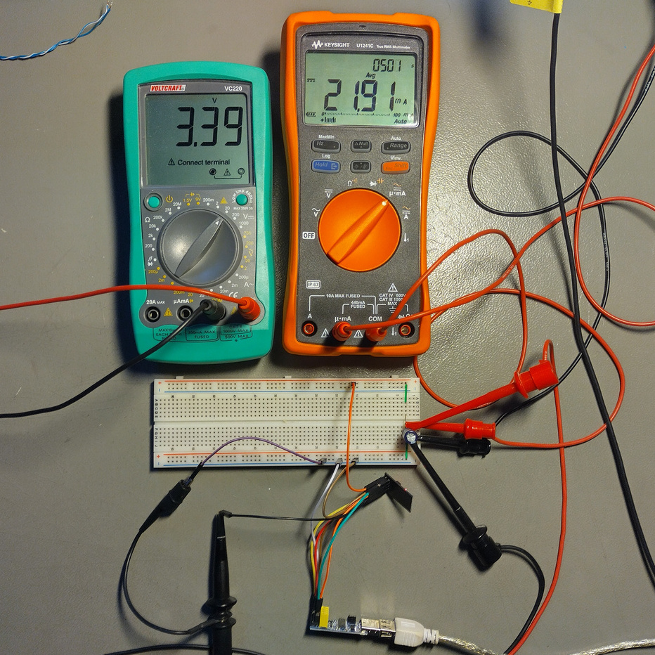
Why does this work? Adding delay(1) actually causes the CPU to spend the vast majority of its time in that one millisecond loop. And counting microseconds turns out to be a far less demanding task, power-wise, than checking for incoming network requests about a hundred thousand times per second. In [Tomaž]’s tests, that one millisecond delay reduced idle power consumption at 3.3 V from roughly 230 mW to around 70 mW — about 60% — while only delaying the web server’s response times by 6-8 milliseconds.

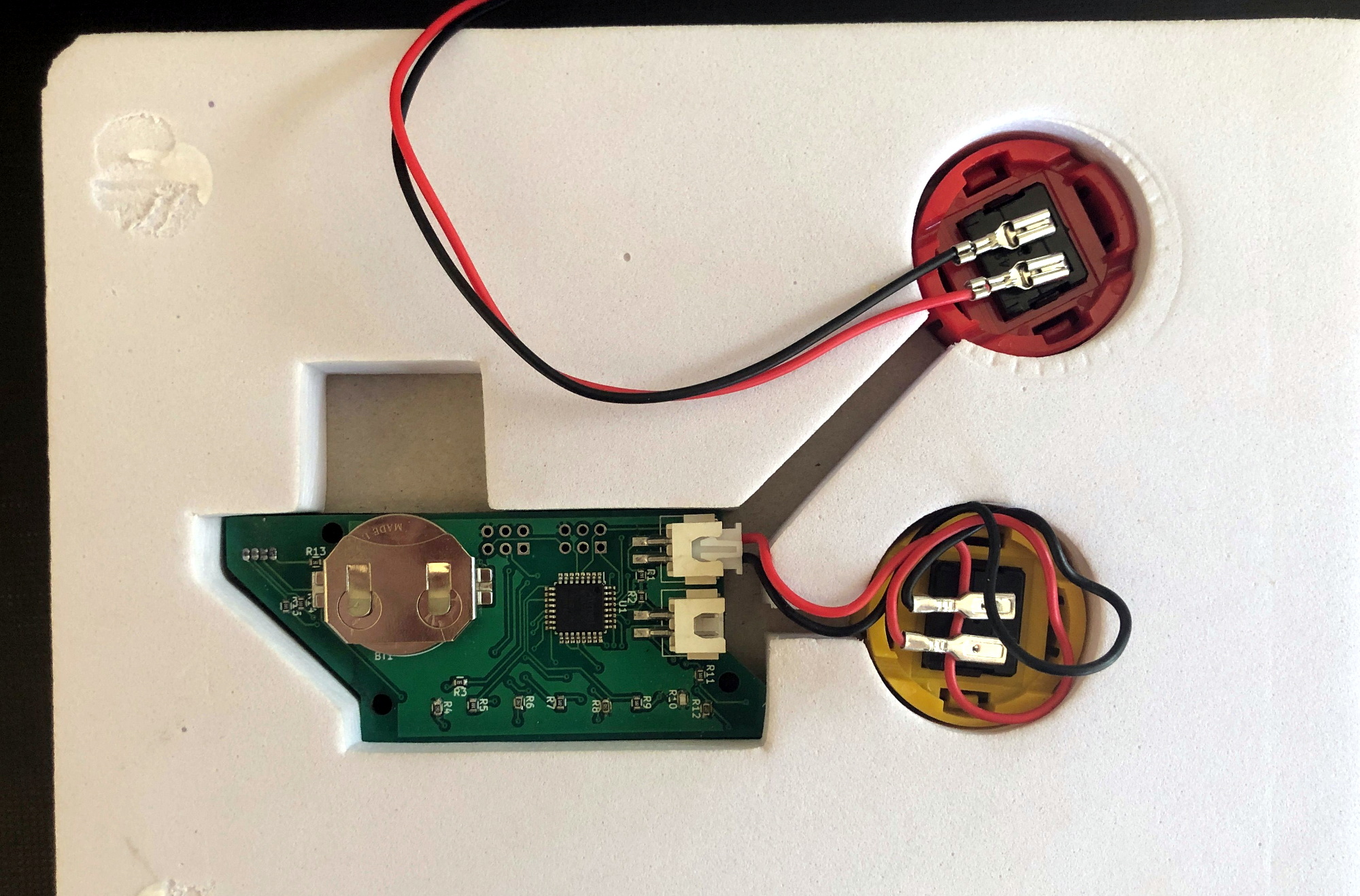
For simple web server applications, this is is for sure a good trick to keep in mind. There are also much more advanced techniques for saving power on ESP8266-based boards; from boards that barely sip a single microamp while sleeping, to coin-cell powered boards that go so far as to modify the TCP/IP stack to help squeeze every bit of power savings possible.

A diagram showing an LED on the left, a lever-style plumbing valve in the center, and an Arduino Uno on the right.

Input devices that can handle rough and tumble environments aren’t nearly as varied as their more fragile siblings. [Alastair Aitchison] has devised a brilliant way of detecting inputs from plumbing valves that opens up another option. (YouTube) [via Arduino Blog]

While [Aitchison] could’ve run the plumbing valves with water inside and detected flow, he decided the more elegant solution would be to use photosensors and an LED to simplify the system. This avoids the added cost of a pump and flow sensors as well as the questionable proposition of mixing electronics and water. By analyzing the change in light intensity as the valve closes or opens, you can take input for a range of values or set a threshold for an on/off condition.

[Aitchison] designed these for an escape room, but we can see them being great for museums, amusement parks, or even for (train) simulators. He says one of the main reasons he picked plumbing valves was for their aesthetics. Industrial switches and arcade buttons have their place, but certainly aren’t the best fit in some situations, especially if you’re going for a period feel. Plus, since the sensor itself doesn’t have any moving parts, these analog inputs will be easy to repair should anything happen to the valve itself.

If you’re looking for more unusual inputs, check out the winners of our Odd Inputs and Peculiar Peripherals contest or this typewriter that runs Linux.

We were impressed with [moononournation’s] tiny thin client project. It claims to use an Arduino, but as you might guess it is using the Arduino software along with a network-enabled microcontroller like an ESP32. The impressive part is that it is standards-compliant and implements VNC’s RFB protocol.

The original coding for RFB on Arduino is from [Links2004] and armed with that, the thin client is probably easier to create than you would guess. However, this project wanted to use a larger screen and found that it led to certain problems. In particular, the original code had a 320×240 display. This project was to use an 800×480 display, but with the limits on the ESP32, the frame rate possible would be under 7 frames per second. The answer was to combine a 16-bit parallel interface with better compression back to the VNC server.

The little keyboard is probably not very practical, but it is compact. That would be another easy thing to modify. Currently, the keyboard uses I2C, but it would be straightforward to change things up. This would be a worthy base to build a bigger project on top. A 3D printed enclosure would be nice, too.

We’ve seen a number of projects built around commercial thin clients. Some from defunct businesses are good sources for obscure parts, too.

[Daumemo] likes experimenting with DIY electronics, and like many people, eventually ran across an AVR microcontroller with a Unified Program and Debug Interface (UPDI). One option is of course to purchase an UPDI programmer, but an even better solution was to make a DIY USB version from nice, cheap parts.

Programming an Attiny404 over the UPDI interface.

UPDI is an interface for external programming and on-chip debugging of microcontrollers, and [Daumemo]’s solution is based on the jtag2updi project. It combines an Arduino Nano (in this case, a clone) with a single resistor, a single capacitor, and a six pin angled header (with a cleverly bent pin) to enable programming UPDI devices over a USB connection. [Daumemo] is happy to report that the device works just fine in both Microchip Studio with AVRDUDE, or PlatformIO.

Is an Arduino Nano a bit overpowered in this role? Maybe, but the price is certainly right. There’s no need for a custom PCB either, since everything can be soldered direct to the Nano board. A matching 3D printed enclosure is about all that’s needed to make a robust and reliable DIY USB UPDI programmer out of a handful of parts, and that sounds good to us.

On the other hand, if you do find yourself making custom PCBs, you may be interested in another of [Daumemo]’s DIY projects: a printable structure to turn a rotary tool into a PCB drill press.

Regular readers will know that Hackaday generally steers clear of active crowdfunding campaigns. But occasionally we do run across a project that’s unique enough that we feel compelled to dust off our stamp of approval. Especially if the campaign has already blasted past its funding goal, and we don’t have to feel bad about getting you fine folks excited over vaporware.

It’s with these caveats in mind that we present to you Computer Engineering for Babies, by [Chase Roberts]. The product of five years of research and development, this board book utilizes an internal microcontroller to help illustrate the functions of boolean logic operations like AND, OR, and XOR in an engaging way. Intended for toddlers but suitable for curious minds of all ages, the book has already surpassed 500% of its funding goal on Kickstarter at the time of this writing with no signs of slowing down.

The electronics as seen from the rear of the book.

Technical details are light on the Kickstarter page to keep things simple, but [Chase] was happy to talk specifics when we reached out to him. He explained that the original plan was to use discreet components, with early prototypes simply routing the button through the gates specified on the given page. This worked, but wasn’t quite as robust a solution as he’d like. So eventually the decision was made to move the book over to the low-power ATmega328PB microcontroller and leverage the MiniCore project so the books could be programmed with the Arduino IDE.

Obviously battery life was a major concern with the project, as a book that would go dead after sitting on the shelf for a couple weeks simply wouldn’t do. To that end, [Chase] says his code makes extensive use of the Arduino LowPower library. Essentially the firmware wakes up the ATmega every 15 ms to see if a button has been pressed or the page turned, and updates the LED state accordingly. If no changes have been observed after roughly two minutes, the chip will go into a deep sleep and won’t wake up again until an interrupt has been fired by the yellow button being pressed. He says there are some edge cases where this setup might misbehave, but in general, the book should be able to run for about a year on a coin cell.

[Chase] tells us the biggest problem was finding a reliable way to determine which page the book was currently turned to. In fact, he expects to keep tinkering with this aspect of the design until the books actually ship. The current solution uses five phototransistors attached to the the MCU’s ADC pins, which receive progressively more light as fewer pages are laying on top of them. The first sensor is exposed when the second page of the book is opened, so for example, if three of the sensors are seeing elevated light levels the code would assume the user is on page four.

Opening to the last page exposes all five light sensors.

The books and PCBs are being manufactured separately, since as you might expect, finding a single company that had experience with both proved difficult. [Chase] plans on doing the final assembly and programming of each copy in-house with the help of family members; given how many have already been sold this early in the campaign, we hope he’s got a lot of cousins.

So what do you do with an Arduino-compatible book when Junior gets tired of it? That’s what we’re particularly interested in finding out. [Chase] says he’s open to releasing the firmware as an open source project after the dust settles from the Kickstarter campaign, which would give owners a base to build from should they want to roll their own custom firmware. Obviously the peripheral hardware of the book is fairly limited, but nothing is stopping you from hanging some sensors on the I2C bus or hijacking the unused GPIO pins.

If you end up teaching your copy of Computer Engineering for Babies some new tricks, we’ve love to hear about it.

What’s this? Another fabulous creation from [Niklas Roy] and [Kati Hyyppä] that combines art and electronics with our zeitgeist and a lot of recycled bits and bobs? You got it. Their workshop in eastern Berlin used to be a retail shop and has a large display window as a result. This seems perfect for a pair of artists in a pandemic, because they can communicate with the community through the things they display in the window. Most recently, it was this interactive cyborg baby we are choosing to call Cybaby.

You might recognize Cybaby as one of the very hackable Robosapien robots, but with a baby doll head. (It also has a single red eye that really pulls its look together.) In the window, Cybaby comes alive and toddles around against a backdrop that grew and evolved over several weeks this spring and summer. Passersby were able to join the network and control Cybaby from outside with their smartphone to make it walk around, press various buttons that change its environment, and trigger a few sensors here and there. Robosapien has been around for about 20 years, so there is already Arduino code out there that essentially simulates its R/C signals. [Niklas] and [Kati] used a NodeMCU (ESP12-E) to send pulses to the IR input of the robot.

Back on the zany zeitgeist front, there’s a hair salon, a convenience store, and a nightclub for dancing that requires a successful trip through the testing center first (naturally). Oh, and there’s a lab next door to the nightclub that can’t be accessed by Cybaby no matter what it tries or how it cries. Check it out after the break.

There’s a dearth of Robosapien posts for some reason, so here’s what [Niklas] and [Kati] had in their window before the World of Cybaby — a really cool pen plotter that prints out messages sent by people walking by.

Want to display a PNG file on a display attached to an Arduino or other microcontroller board? You’ll want to look at [Larry Bank]’s PNGdec, the Arduino-friendly PNG decoder library which makes it much easier to work with PNG files on your chosen microcontroller.

The PNG image format supports useful features like lossless compression, and was generally developed as an improved (and non-patented) alternative to GIF files. So far so great, but it turns out that decoding PNG files on a microcontroller is a challenge due to the limited amount of memory compared to desktop machines. When the PNG specification was developed in the 90s, computers easily had megabytes of memory to work with, but microcontrollers tend to have memory measured in kilobytes, and lack high-level memory management. [Larry]’s library addresses these issues.

PNGdec is self-contained and free from external dependencies, and also has some features to make converting pixel formats for different display types easy. It will run on any microcontroller that can spare at least 48 K of RAM, so if that sounds useful then check out the GitHub repository for code and examples.

We’ve seen [Larry]’s wonderful work before on optimizing GIF playback as well as rapid JPEG decoding, and these libraries have increasing relevance as hobbyists continue to see small LCD and OLED-based displays become ever more accessible and affordable.

[PNG logo: PNG Home Site]

Why buy a num pad or a macropad when you can build something new and beautiful, open source that bad boy, and be a hero to the community? We think that should be all the justification you ever need to build instead of buy, even if you think your thing is Just Another Keypad [JAnK] as [Clewsy] claims.

At first glance, JAnK appears to be a standard number pad with four macro keys across the top. But when you roll your own ‘board, all the keys are programmable. [Clewsy] took advantage of this by adding a second layer that’s accessible with (what else?) the Num Lock key. This switches JAnK over to 21-key macro pad mode.

[Clewsy] rolled their own PCB for this and used the venerable ATMega32u4 because of its HID and USB host capabilities. Every key is backlit, and these LEDs are driven by an MP3202 LED driver and PWM from the AVR. [Clewsy] was able to build a prototype by sawing the num pad off of a stainless steel key switch plate from another build, but eventually ordered JAnK its own custom, laser-cut, stainless steel plate. The lovely enclosure is made of spotted gum wood and an acrylic base.

Putting it all together proved to be a bit problematic. [Clewsy] soldered up the minimum viable components for testing and discovered that the ATMega’s VCC and GND pins were both shorted. This killed the AVR programmer, but not the chip itself, and [Clewsy] happened to have a spare. To add insult to injury, the Num Lock light didn’t work, but [Clewsy] was able to simply reverse the LED instead of ordering a new pile of boards. Check out the detailed write-up with code and tons of pictures over on [Clewsy]’s personal site.

One of the awesome things about this build is that [Clewsy] was able to re-use the code from macr0, which began life as a proof of concept for scanning key matrices, and retired to become a music and media controller.

You really should learn to read Morse code. But if you can’t — or even if you can, and just want a break — you can always get a computer to do it. For example, [jmharvey1] has a decoder that runs on a cheap Bluepill dev board.

The device uses a touchscreen and a few common components. The whole thing cost about $16. You can see it at work along with a description of the project in the video below.

The code uses the Arduino-style setup for the Blue pill — something we’ve talked about before. As for the decoding method, the software employs the Goertzel algorithm which is akin to a single frequency Fourier transform. That is, while a full transform gives you information about the frequency component of a signal across a wide range, the Goertzel algorithm probes the signal for one or a small number of distinct frequencies.

The decoder table looks confusing at first until you realize that each “decode” value consists of a 1 as a start bit followed by a 1 for a dash and a zero for a dot. All bits to the left of the start bit don’t count. So an “E” codes as 02 hex — a start bit followed by a single zero or dot. A “C” is 1A hex (1 + -.-.). Once you find the matching code, you apply the same index to another table to look up the actual letter or string of letters.

If you buy a Bluepill to make one of these, you might as well get two and build something to send code, too.

We often like to say that if something is worth doing, then it’s worth overdoing. This automatic cat feeder built by [krizzli] is a perfect example of the principle. It packs in far more sensors and functions than its simple and sleek outward appearance might suggest, to the point that we think this build might just set the standard for future projects.

The defining feature of the project is a load cell located under the bowl, which allows the device to accurately measure out how much feed is being dispensed by weight. This allows the feeder to do things such as detect jams or send an alert once it runs out of food, as well as easily adjust how much is dispensed according to the animal’s dietary needs. To prevent any curious paws from getting into the machine while it’s doling out the food, the lid will automatically open and close during the filling process, complete with optical sensors to confirm that it moved as expected.

All of the major components of the feeder were printed out on a Prusa i3 MK3S, and [krizzli] says that the feed hopper can be scaled vertically if necessary. Though at the current size, it’s already packing around a week’s worth of food. Of course, this does depend on the particular feline you’re dealing with.

In terms of electronics, the feeder’s primary control comes from an ESP8266 (specifically, the Wemos D1 Mini), though [krizzli] also has a Arduino Pro Mini onboard so there’s a few more GPIO pins to play with. The food is dispensed with a NEMA 17, and a 28-BYJ48 stepper is in charge of moving the lid. A small OLED on the side of the feeder gives some basic information like the time until the next feeding and the dispensed weight, but there’s also a simple API that lets you talk to the device over the network. Being online also means the feeder can pull the time from NTP, so kitty’s mealtime will always be on the dot.

Over the years we’ve seen an incredible array of automatic cat feeders, some of which featuring the sort of in-depth metrics possible when you’ve got on onboard scale. But we can’t help but be impressed with how normal this build looks. If nothing else, of all the feeders we’ve seen, this one is probably the most likely to get cloned and sold commercially. They say it’s the most sincere form of flattery.


  • Newsletter

    Sign up for the PlanetArduino Newsletter, which delivers the most popular articles via e-mail to your inbox every week. Just fill in the information below and submit.

  • Like Us on Facebook