Posts | Comments

Planet Arduino

Archive for the ‘74HC595’ Category

In this article we examine another style of vintage display technology – the incandescent seven-segment digital display. We are using the FFD51 by the IEE company (data sheet.pdf) – dating back to the early 1970s. Here is a close-up of our example:

You can see the filaments for each of the segments, as well as the small coiled ‘decimal point’ filament at the top-right of the image above.  This model has pins in a typical DIP format, making use in a solderless breadboard or integration into a PCB very simple:

It operates in a similar manner to a normal light bulb – the filaments are in a vacuum, and when a current is applied the filament glows nicely. The benefit of using such as display is their brightness – they could be read in direct sunlight, as well as looking good inside.  At five volts each segment draws around 30mA. For demonstration purposes I have been running them at a lower voltage (3.5~4V), as they are old and I don’t want to accidentally burn out any of the elements.

Using these with an Arduino is very easy as they segments can be driven from a 74HC595 shift register using logic from Arduino digital out pins. (If you are unfamiliar with doing so, please read chapters four and five of my tutorial series). For my first round of experimenting, a solderless breadboard was used, along with the usual Freetronics board and some shift register modules:

Although the modules are larger than a DIP 74HC595, I like to use these instead. Once you solder in the header pins they are easier to insert and remove from breadboards, have the pinouts labelled clearly, are almost impossible to physically damage, have a 100nF capacitor for smoothing and a nice blue LED indicating power is applied.

Moving forward – using four shift register modules and displays, a simple four-digit circuit can be created. Note from the datasheet that all the common pins need to be connected together to GND. Otherwise you can just connect the outputs from the shift register (Q0~Q7) directly to the display’s a~dp pins.

Some of you may be thinking “Oh at 30mA a pin, you’re exceeding the limits of the 74HC595!”… well yes, we are. However after several hours they still worked fine and without any heat build-up. However if you displayed all eight segments continuously there may be some issues. So take care. As mentioned earlier we ran the displays at a lower voltage (3.5~4V) and they still displayed nicely. Furthermore at the lower voltage the entire circuit including the Arduino-compatible board used less than 730mA with all segments on –  for example:

 For the non-believers, here is the circuit in action:

Here is the Arduino sketch for the demonstration above:

Now for the prototype of something more useful – another clock. :) Time to once again pull out my Arduino-compatible board with onboard DS1307 real-time clock. For more information on the RTC IC and getting time data with an Arduino please visit chapter twenty of my tutorials. For this example we will use the first two digits for the hours, and the last two digits for minutes. The display will then rotate to showing the numerical day and month of the year – then repeat.

Operation is simple – just get the time from the DS1307, then place the four digits in an array. The elements of the array are then sent in reverse order to the shift registers. The procedure is repeated for the date. Anyhow, here is the sketch:

#include "Wire.h"
#define DS1307_I2C_ADDRESS 0x68
// note the digital pins of the arduino that are connected to the nixie driver
int clockPin = 7;
int latchPin = 8;
int dataPin = 9;
int clockArray[5]; // holds the digits to display
int a=0;
// the bits represent segments a~dp from left to right
// if you add one to the number (or turn on the last bit) the decimal point turns on
byte numbers[]={
 B11111100, // digit zero
 B01100000,
 B11011010,
 B11110010,
 B01100110,
 B10110110,
 B10111110,
 B11100000,
 B11111110,
 B11110110}; // digit nine
// Convert normal decimal numbers to binary coded decimal
byte decToBcd(byte val)
{
 return ( (val/10*16) + (val%10) );
}
// Convert binary coded decimal to normal decimal numbers
byte bcdToDec(byte val)
{
 return ( (val/16*10) + (val%16) );
}
void setDateDs1307(byte second, // 0-59
byte minute, // 0-59
byte hour, // 1-23
byte dayOfWeek, // 1-7
byte dayOfMonth, // 1-28/29/30/31
byte month, // 1-12
byte year) // 0-99
{
 Wire.beginTransmission(DS1307_I2C_ADDRESS);
 Wire.send(0);
 Wire.send(decToBcd(second)); // 0 to bit 7 starts the clock
 Wire.send(decToBcd(minute));
 Wire.send(decToBcd(hour)); 
 Wire.send(decToBcd(dayOfWeek));
 Wire.send(decToBcd(dayOfMonth));
 Wire.send(decToBcd(month));
 Wire.send(decToBcd(year));
 Wire.send(0x10); // sends 0x10 (hex) 00010000 (binary) to control register - turns on square wave
 Wire.endTransmission();
}
// Gets the date and time from the ds1307
void getDateDs1307(byte *second,
byte *minute,
byte *hour,
byte *dayOfWeek,
byte *dayOfMonth,
byte *month,
byte *year)
{
 // Reset the register pointer
 Wire.beginTransmission(DS1307_I2C_ADDRESS);
 Wire.send(0);
 Wire.endTransmission();
 Wire.requestFrom(DS1307_I2C_ADDRESS, 7);
 // A few of these need masks because certain bits are control bits
 *second = bcdToDec(Wire.receive() & 0x7f);
 *minute = bcdToDec(Wire.receive());
 *hour = bcdToDec(Wire.receive() & 0x3f); // Need to change this if 12 hour am/pm
 *dayOfWeek = bcdToDec(Wire.receive());
 *dayOfMonth = bcdToDec(Wire.receive());
 *month = bcdToDec(Wire.receive());
 *year = bcdToDec(Wire.receive());
}
void setup()
{
 byte second, minute, hour, dayOfWeek, dayOfMonth, month, year;
 pinMode(latchPin, OUTPUT);
 pinMode(clockPin, OUTPUT);
 pinMode(dataPin, OUTPUT);
 Wire.begin();
// Change these values to what you want to set your clock to.
 // You probably only want to set your clock once and then remove
 // the setDateDs1307 call.
second = 00;
 minute = 35;
 hour = 17;
 dayOfWeek = 5;
 dayOfMonth = 29;
 month = 4;
 year = 12;
 // setDateDs1307(second, minute, hour, dayOfWeek, dayOfMonth, month, year);
}
void showTime()
{
 byte second, minute, hour, dayOfWeek, dayOfMonth, month, year;
 getDateDs1307(&second, &minute, &hour, &dayOfWeek, &dayOfMonth, &month, &year);

 if (hour<10)
 {
 clockArray[1]=0;
 clockArray[2]=hour;
 }
 if (hour>9)
 {
 clockArray[1]=int(hour/10);
 clockArray[2]=hour%10;
 } 
 if (minute<10)
 {
 clockArray[3]=0;
 clockArray[4]=minute;
 }
 if (minute>9)
 {
 clockArray[3]=int(minute/10);
 clockArray[4]=minute%10;
 }
 displayArray();
}
void showDate()
{
 byte second, minute, hour, dayOfWeek, dayOfMonth, month, year;
 getDateDs1307(&second, &minute, &hour, &dayOfWeek, &dayOfMonth, &month, &year);

 if (dayOfMonth<10)
 {
 clockArray[1]=0;
 clockArray[2]=dayOfMonth;
 }
 if (dayOfMonth>10)
 {
 clockArray[1]=int(dayOfMonth/10);
 clockArray[2]=dayOfMonth%10;
 }
 if (month<10)
 {
 clockArray[3]=0;
 clockArray[4]=month;
 }
 if (month>10)
 {
 clockArray[3]=int(month/10);
 clockArray[4]=month%10;
 }
 displayArray();
}
void displayArray()
// sends the data from clockArray[] to the shift registers
{
 digitalWrite(latchPin, LOW);
 shiftOut(dataPin, clockPin, LSBFIRST, numbers[clockArray[4]]); // digit 4 
 shiftOut(dataPin, clockPin, LSBFIRST, numbers[clockArray[3]]); // digit 3 
 shiftOut(dataPin, clockPin, LSBFIRST, numbers[clockArray[2]]+1); // digit 2 and decimal point
 shiftOut(dataPin, clockPin, LSBFIRST, numbers[clockArray[1]]); // digit 1
 digitalWrite(latchPin, HIGH);
}
void loop()
{
 showTime(); // display the time 
 delay(5000);
 showDate(); // display the date (day and month) for two seconds
 delay(2000);
}

and the clock in action:

So there you have it – another older style of technology dragged into the 21st century. If you enjoyed this article you may also like to read about vintage HP LED displays. Once again, I hope you found this article of interest. Thanks to the Vintage Technology Association website for background information.

Have fun and keep checking into tronixstuff.com. Why not follow things on twitterGoogle+, subscribe  for email updates or RSS using the links on the right-hand column, or join our Google Group – dedicated to the projects and related items on this website. Sign up – it’s free, helpful to each other –  and we can all learn something.

The post Arduino and FFD51 Incandescent Displays appeared first on tronixstuff.

Aug
01

Announcement – August Competition!

74HC595, competition, DSO, JYE Tech, LED, LM3914, MSP430, RGB, RGB LED, TLC5940, tronixstuff Comments Off on Announcement – August Competition! 

Hello everyone!

During July there was another competition which was quite fun, so from August and onwards we shall do it again. The winner ‘S.R.’ won the minor prize so the major prize jackpots into this month. Running these competitions are a way of saying thank you to my readers, and to generate some interaction. So …

All you have to do for a chance to win is the following:

  1. Read the blog posts and articles in August, as there will be six questions you will need to answer placed randomly amongst the posts. To keep track, subscribe using one of the methods on the right hand side of this page
  2. When you have answers for all six questions, email them to competition@tronixstuff.com
  3. If you follow me on twitter (@tronixstuff) and retweet one post in August, you will receive two entries, so put your twitter address in your email.
  4. On September the 1st, all the email addresses will be placed in a random draw and one selected. If the entry drawn has all six questions correct, they will win the major prize!
  5. If the first entry drawn does not have six correct answers, they will win the minor prize, and the major prize will carry over until September, to be combined with the new major prize.

The prizes!

Major prize

The major prize for August consists of the following:

  • One assembled, used JYE Tech Digital Storage Oscilloscope – from the kit review;
  • One new pair of 315 MHz wireless data modules, as used in Getting Started with Arduino – Chapter Eleven;
  • And something different, the new Texas Instruments MSP430 Launchpad kit, including evaluation board, two MCUs  and the USB cable.

Minor prize

The minor prize for August is John’s Fun with LEDs! pack, consisting of:

  • ten each of red, green, yellow and orange 5mm LEDs;
  • four RGB 10mm diffused LEDs
  • three 74HC595 shift registers
  • two Texas Instruments TLC5940 16-channel LED driver ICs
  • two LM3914 bar graph/dot driver ICs
  • 20 x 560 ohm 1% resistors (they missed the photo call)

Hopefully everyone can have some fun reading about electronics and learning along the way. As with any competition, there are a few rules:

  1. If you have won a previous competition, you cannot enter
  2. If you know me personally, you cannot enter
  3. The prizes carry no warranty, we accept no liability for anything at all that they may cause
  4. Prizes only include what is in the photograph, and will be sent via standard airmail free of charge
  5. My decision is final
  6. You can witness the draw in person with prior arrangement
  7. The time used is Australian Eastern Standard Time (GMT: +10)

If you cannot wait for a chance to win, the DSO and and a range of LEDs are available from our friends at Little Bird Electronics.

So keep your eyes peeled and have fun!

Hello readers!

Today we are going to examine the 74HC4066 quad bilateral switch IC. My reason for writing this comes from a comment left by a reader on chapter nine of the Arduino tutorial. They suggested using a 4066 IC to control the cathodes of the LED matrix instead of resistors and NPN transistors. This was a good suggestion, however the 4066 can only switch a current of 10mA per pin. Luckily the 74HC4066 can handle up to 25mA per switch – so we’ll look into this instead.

First of all, let’s say hello:

This is the 14-pin DIP package. It is also available in surface mount, and other newer package styles. Although we are looking at an example from NXP, according to my main component supplier (Farnell/Newark) this IC is also manufactured by Texas Instruments, ON Semi, ST Microelectronics and Fairchild.

So, what is a quad-bilateral switch? Four switches in one IC. Here is a diagram:

Imagine a simple normally-open push button. You press the button, and current can flow through the switch. Using the 74HC4066, when current is applied to the E pin, current can pass through from the matching Y pin to the Z pin. As you can see above, there are four of these switches in the IC. This is where the benefit of the IC comes to mind, normally one might use a 1k ohm resistor and an NPN switching transistor as an electronic switch, and I have done so myself. But when you need a few of them, it can be easier to start using these 74HC4066s as long as the current requirements are met.

With regards to the current the IC can switch, Is, the maximum is 25mA per switch. This is more than enough to run a typical LED, TTL logic gate, etc. The other interesting parameter is the turn-on and turn off times – at 6 volts it can turn on in around 10 nanoseconds and turn off at around 13 nanoseconds (so a rough calculation – say it takes 30 nanoseconds to switch on and then switch off, that’s 33.3 million times per seconds (33.3 MHz). All these parameters and more are available from the data sheet (pdf). Someone correct me if I’m wrong!

That’s enough theory – let’s put it to work now. Our first demonstration is quite simple – just switch on and off some LEDs via a 74HC595 shift register and an Arduino. We send a number (0, 1, 2, 4, 8 ) to the shift register, which stays off, then sets pins Q0, Q1, Q2, Q3 high in order, which in turn activate the switches 1~4 on the 74HC4066. The 74HC4066 sends a current to each LED connected to the switch outputs.

Here is the schematic:

Laid out on the breadboard:

And the ubiquitous video:

And here is the Arduino sketch: demo1.pdf. Well that was interesting. I know these simple demonstrations may be… well a little simple, but after taking the time to build them from scratch you get a better understanding of the part and how they work. Practice makes perfect and all that. Anyhow, let’s have a look at something much more interesting – a very basic (!) digital to analogue converter. Consider the circuit below:

The 74HC4066 switches creates a final voltage through the sum of various currents being switched into the final output. First of all, here is a video of the switches being turned on and off one at a time:

and the corresponding Arduino sketch:demo2.pdf. The next video shows the results of sending decimal numbers 0~15 to the shift register – in effect continually adding the outputs of the pins until all pins are on, then in reverse:

and the corresponding Ardiono sketch:demo3.pdf.

Well I hope you found this part review interesting, and helped you think of something new to make. In conclusion I would consider the 74HC4066 easier and quicker for end user to use in projects (less pins to solder, etc) however using it could cost more depending on the volume required. Furthermore, this would only apply if the current restrictions of the IC are met.

As always, thank you for reading and I look forward to your comments and so on. Furthermore, don’t be shy in pointing out errors or places that could use improvement. Please subscribe using one of the methods at the top-right of this web page to receive updates on new posts. Or join our new Google Group. High resolution photos are available on flickr.

Otherwise, have fun, be good to each other – and make something! :)

Notes: In writing this post, I used information from NXP, plus information and circuit inspiration from various books by Forrest Mims III.

Thank you!


This is part of a series titled “Getting Started with Arduino!” by John Boxall – A tutorial on the Arduino microcontrollers, to be read with the book “Getting Started with Arduino” (Massimo Banzi).

The first chapter is here.

Welcome back fellow arduidans!

Just a note: this is the tenth instalment, I hope you have been enjoying the posts, and I sincerely thank you for reading. Let’s go!

This week we will start looking at LED matrix displays, designing user interfaces, implementing a user interface for  a clock, and finish up making an alarm clock.

Firstly, let’s have plenty of fun with 64 LEDs! Using an 8×8 LED display module:

Previously we have used 74HC595 shift registers to drive strips of LEDs, single and four-digit LED displays. An LED matrix seems complex at first, but after further investigation quite simple. With sixteen pins you can control 64 LEDs. It works by having 8 row pins, each pin connected to all the anodes on one row; and 8 pins each connected to the cathodes on one column:

It does look like a mess, but we can work it out. As we did with the 4-digit 7-segment display module, we just need one shift register for the anodes, and one for the cathodes. Moving along from exercise 6.2, it will be easy to drive the an LED matrix display – one shift register (the left hand side) will apply current to the rows (anodes) and the other shift register will apply current to NPN transistors to allow current to flow from the cathodes (columns) to ground. So we can make an example quite easily. You will need:

  • Your standard Arduino setup (computer, cable, Duemilanove or compatible)
  • One 8×8 LED matrix. Try to find one that has LEDs with a forward voltage of 2 volts and a current of less than 20mA. If it is bicolour, that’s ok – just use one colour for now
  • Eight 560 ohm 1/4 watt resistors
  • Eight 1 kilo ohm 1/4 resistors
  • Eight BC548 NPN transistors
  • Two 74HC595 shift registers
  • Solderless breadboard and connecting wires

Here is a circuit diagram for our example (click on it to enlarge):

Please note that there are eight transistor/resistor combinations from the second shift register – I just have not drawn them in to save my sanity. They’re on the bottom right of my board:

Now how are we going to light up those LEDs? We need to send two bytes of data to the shift registers, one byte for the row, and one for the column. For this example we will work with individual pixels. For example, say you want to turn on the pixel at 8 across, 8 down – the bottom right. You need to send the following bytes of data to the shift registers: b00000001 and b00000001. In decimal those two numbers are 128 and 128. Or the top-left LED, at 1 across, 1 down – it would be b10000000, b10000000 or decimal 1,1. Once again we can use the functions:

digitalWrite(latchpin, LOW);
shiftOut(datapin, clockpin, MSBFIRST, 1); // byte of data for the right-hand shift register (cathode controller)
shiftOut(datapin, clockpin, MSBFIRST, 1);  // for the left-hand shift register (anode controller)
digitalWrite(latchpin, HIGH);

… to send the data to the shift registers. This example sketch for the above circuit should be pretty well self-explanatory if you have been following my tutorials: Example 9.1.pdf.

Here is is in action:

Once again, quite mesmerising. Did you notice that the horizontal solid rows were dimmer than the solid vertical columns? This is because when you light up one row, all eight LEDs are drawing current from one pin of the shift register – so there is less current for each LED; whereas in the column, each LED has its own source of current, so can therefore operate at full brightness. So a hint – when you are creating images or characters for your display, use scrolling columns to display the image.

Experiment with the example 9.1 sketch, if you display only vertical columns, and make the delay zero – you can give the illusion that the entire display is on, but it is not.

Which leads us into the first exercise for the week!

Exercise 9.1

We can display entire columns with our matrix display. We can position these columns on demand. And without a delay, fill up the entire matrix. Now you can create images, or characters and display them on the matrix, one column at a time. For example, the little yellow dude from that popular arcade game many years ago might look like this:

Using the circuit described for example 9.1, create a character, shape, or whatever tickles your fancy, and animate it to move across the screen. To make it easier to calculate the byte values for the columns, I have placed a spreadsheet to use in our Google Group’s file section (matrix-ss.xls or .odt).

Hint – To animate an image, you will need to map the matrix every time the image changes – just like a normal animation or cartoon. However, store all the values for the entire animation in one array, otherwise you will go bonkers. When you need to read the array, each matrix image can be read as they are multiples of eight (then add the reference to the value you want).

For inspiration, here is what I came up with:

and the corresponding exercise 9.1.pdf.

How did you go? If you have an interesting animation, and you can do so – please email a link to Youtube, Vimeo, etc showing your creation – you could win a prize.

Time to get a little more serious now. :(

Over time you have been making things, some useful, some more experimental than anything. Hopefully you will reach the stage of designing something that has a real-world use and could be used by people other than yourself or your immediate circle of friends. In the next few weeks we will look at methods of transitioning projects from prototypes to standalone products you can develop!

A major part of your design should be the user interface, or how your project responds to user input and displays data, results and so on. If something is difficult to use, or understand, it will not be a good product. So what can we do about this? This week we will examine the clock made in example 7.4 and change it to be independent of a computer, and easy for the user to operate. But now for some design inspiration…

The humble alarm clock (it has been staring at me every morning). Here is my late grandfather’s clock from the 1960s:

Simple, yet functional. It does what it is supposed to do with the minimum of fuss. (It’s German). And that is how our project user interfaces should be. As technical people it is very easy to get carried away and put buttons, lights, and all sorts of things together, but at the end of the day, less is more. How can we emulate this with Arduino – but in a simple method?

Looking at the face of the clock, it displays the time (hours, minutes, seconds) and the alarm time. We can use an LCD for that. On the top is the alarm off button. We can use a button for that. On the rear there are winders for the time and alarm spring – we have electricity for that. There are two knobs, one to adjust the time, and one to adjust the alarm – here we have several options. We could use up/down buttons… perhaps we could use a knob as well? And finally there is the gain control – we don’t need this as our DS1307 is infinitely more accurate.

A rough map of how you want things to work is always a good start, for example my mess below:

How can this be implemented? Let’s see. The clock will normally display the date, time, etc. If a button is pressed, it will switch to menu mode (on the right). A knob will be used to select one of the options listed on the right, when the required option is displayed, the user presses the button to select the option. Then the user can use the knob to adjust the variable for that option, and press the button to return to the menu. The last menu option is to return to the clock display. So we can control the whole lot with only one button and one knob.

The button is easy with Arduino, and to save money we can use a potentiometer as a knob. Remember we did this in in exercise 6.2. Normally it can return a value between 0 and 1023, but with our clock we need it to return a value that falls within a variety of ranges – from 0 to 6 for day of the week, to 0 to 59 for the minute adjustment.

Exercise 9.2

Create a function to use a potentiometer to return an integer between zero and a maximum range value. The function will accept the maximum range value, and return an integer which represents the position of the knob. For example:

int dialposition(int maxrange);

Here is a short video of my interpretation in action.

And the resulting sketch: exercise 9.2.pdf. The value rangemax that is fed into the function is the number of positions in the range you want to work with. For example, if I want the knob to return a value between zero and fifty-nine (sixty values in the range) I would set rangemax to 60. The value dialpin is the number of the analogue pin the potentiometer is connected to. You should use a linear potentiometer to ensure a nice smooth adjustment.

Great – now we have a way of reading our knob and customising the result for our range requirements. Our clock example’s menu will require eight options, each with their own function (e.g. set hours, set minutes, set year, return to clock, etc). We have one button, so you could use that to trigger an interrupt to start the menu display (interrupts were covered in chapter three). However if you have made an LCD shield use the interrupt pins, you will need to check the button status while displaying the time. We will make the display of the menu a separate function as well.

For now we will make our clock respond to the ‘menu’ button, and display the eight options when the knob is rotated. We will build on the sketch from example 7.4. Here is the result of doing this:

… and the resulting sketch: example 9.2.pdf.

Now it is time (ha!) to make those menu options actually do something. First we need our displaymenu() function to call the selected option. This can be done with a switch…case function. For example, I will put this code after the while loop:

  switch(readdial(8,1))

  {

    case 0: msethours; break;

    case 1: msetminutes; break;

    case 2: mset1224; break;

    case 3: msetday; break;

    case 4: msetmonth; break;

    case 5: msetyear; break;

    case 6: msetdow; break;

  }

There is no need for a seventh option (return to clock display) as this will default if the knob is in the ’7′ range. Notice I have already declared the name of the functions to call. All we have to do is create the individual functions. However there is one catch to work around, when it comes to setting time and date data, this is all done with the one function:

setDateDs1307(second, minute, hour, dayOfWeek, dayOfMonth, month, year);

So inside the function that (for example) sets the hour, immediately before setting the hour, read the rest of the values from the clock, and reset them back in with the setDateDS1307() function.

Once again the basic work has been done for you, please see this video:

… and the sketch: example 9.3.pdf. Although the contents of the LCD during the menus may be brief, the framework of the user interface has been created and can now be easily modified. For example, if you had a 20 x 4 character LCD, you could offer more help to the user.

But returning to the original task – emulating Grandfather’s alarm clock. We need an alarm!

Exercise 9.3

You guessed it – modify the clock in example 9.3 to have an alarm as well. User can set the alarm, and turn it on or off with the menu system. When the alarm sounds, the user should be able to turn off the alarm, Have fun!

How did you go? Here is a video demonstration of my work:

… and the sketch: exercise 9.3.pdf. That was really fun – I have a lot more clock ideas now.

I hope you enjoyed the change of pace this week and have a greater understanding on why we should create simpler human-machine interfaces wherever possible.

Well that is another week over. However, as usual I’m already excited about writing the next instalment… Congratulations to all those who took part and built something useful!

Please subscribe (see the top right of this page) to receive notifications of new articles.

High resolution photos are available from flickr.

If you have any questions at all please leave a comment (below). We also have a Google Group dedicated to the projects and related items on the website – please sign up, it’s free and we can all learn something. If you would like to showcase your work from this article, email a picture or a link to john at tronixstuff dot com. You might even win a prize!

Don’t forget to check out the range of gear at Little Bird Electronics!

So have fun, stay safe and see you soon for our next instalment!


May
16

Getting Started with Arduino! – Chapter Six addendum

74HC595, arduino, Arduino Tutorial, education, learning electronics, microcontrollers Comments Off on Getting Started with Arduino! – Chapter Six addendum 

This is part of a series titled “Getting Started with Arduino!” – A tutorial on the Arduino microcontrollers, to be read with the book “Getting Started with Arduino” (Massimo Banzi).

The first chapter is here.

Welcome back fellow arduidans!

After reviewing Chapter Six of our tutorials, I felt that there was some important information missing about the section regarding driving 4-digit 7-segment LED display modules. Although we have discussed displaying numbers using the module, and hopefully you have done this yourself with exercise 6.2, those numbers were constantly being written to the display as the sensor was being repeatedly read.

But how do we send a number to the display – and hold it there? We need a function that can accept the number to display – and the length of time (in cycles) to hold it there. I have rewritten the function displaynumber() from the solution to exercise 6.2 – now it accepts another value, “cycles”. This is the number of times the number will be shown on the display.

void displaynumber(int rawnumber, int cycles)
// takes an integer and displays it on our 4-digit LED display module and HOLDS it on the display for ‘cycles’ number of cycles
{
for (int q=1; q<=cycles; q++)
{
if (rawnumber>=0 && rawnumber<10)
{
onedigitnumber(rawnumber);
}
else if (rawnumber>=10 && rawnumber<100)
{
twodigitnumber(rawnumber);
}
else if (rawnumber>=100 && rawnumber<1000)
{
threedigitnumber(rawnumber);
}
else if (rawnumber>=1000)
{
fourdigitnumber(rawnumber);
}
}
}
Here is a sketch to demonstrate this function, the hardware is the same as exercise 6.2, except there is no need for the variable resistor: exercise6p2addendum.pdf.

And my day wouldn’t be complete without another video demonstration. This example has cycles set to 500.

So there you have it! Now you have the knowledge to use these multi-digit displays effectively. And now that we have mastered them, we can move onto more interesting and useful display types. To find out, subscribe using the methods at the top right of this web page – and join our Google Group!

So have fun, stay safe and see you soon for our next instalment!


This is part of a series titled “Getting Started with Arduino!” – A tutorial on the Arduino microcontrollers, to be read with the book “Getting Started with Arduino” (Massimo Banzi).

The first chapter is here.

Welcome back fellow arduidans!

Hello once again to our regular Arduino tutorial instalment. This week are up to all sorts of things, including: distance sensing, using prototyping shields, even more shiftiness with shift registers and 4-digit 7-segment displays, and some exercises to refresh and expand your knowledge. Wow – let’s get cracking…

Do you know how to keep your distance? Some people do, some do not. The same goes for mechatronical things (i.e. robots, those little autonomous vacuum cleaners, etc). So to solve that problem you can integrate a distance sensor into your design. Hopefully by following this section you will gain an understanding of such sensors, and be able to make use of them later on in your own projects. Anyhow, today we are looking at the Sharp GP2Y0A21YK0F infra-red distance sensor. What a mouthful… The funny thing is that it looks like a robot head:

That white JST connector is for three leads, +5V, GND, and analogue out. When purchasing it you should also get a matching lead to save time and mucking about.

How it works is quite simple (I must stop writing that, some things are not as simple as they seem…) – the sensor contains an infra-red transmitter and a receiver. It returns a voltage that is relative to the distance between itself and the object in front of it. This output voltage is inversely proportional to the distance; which is explained better with this graph from the data sheet:

However it is always fun to test these things out yourself. So I placed a sensor up over my desk, measured out 80cm, and attached the multimeter to the analogue output of the sensor.

A crude setup but effective. I held a white piece of cardboard in front of the sensor, starting from more than one metre away, then moved closer to the minimum, then back out again. As shown in this video clip:

Although watching that multimeter may not have been too interesting, hopefully the next task will be!

Exercise 6.1

Using the values from the graph from the Sharp data sheet (above), make yourself a distance-measuring device. Use an LCD module to display the measurements. Metric and imperial! This shouldn’t be too hard at all, you’re just using one analogue input from the sensor, some basic maths, and displaying some data on an LCD. Furthermore, to make it truly portable, you could wire up a 9v PP3 battery to a DC plug and use it for power. A hint – before calculating distances, run a sketch to just return the analogRead() value from the sensor. Then you can make your own judgement on voltage-distance calculations. To save time I used the Electronic Bricks to rapidly construct this prototype.

You will need:

Anyhow, here is a photo of what I came up with:

and the ubiquitous video clip

Finally, my sketch for the solution: Exercise 6.1.pdf. You may have to adjust the values in the decision tree for more accuracy. After spending some time with this sensor, I wouldn’t rely on it for exact distance calculations, however it would be very useful for general item detection, air switches and so on. In the next week or two we will examine another type of distance sensor.

What else could this be used for? Robotics sensors, burglar alarms, switching things on and off. Hopefully you have gained some knowledge about this sensor and have some ideas for implementation.

Coffee time.

Now that we have spent a few weeks constructing our prototypes on breadboards and electronic bricks, it is now time to look at how we can do this in a more compact, and/or permanent method. As you already know, the Arduino system allows for “shields”, PCBs that plug on top of your Arduino board to add some sort of extra functionality. One of these was the Electronic Brick chassis, another popular shield is the ethernet shield.

Well that’s all very nice, but can we do this ourselves? Of course. You need a prototyping shield. There are two main types of protoshield, one that contains a small solderless breadboard that can be used on the shield:

or a shield that is plainly a PCB, ready to solder a circuit onto it. This one below is great, it includes two extra LEDs and a button. Furthermore, the yellow PCB makes things easier to see:

As you can imagine, one is more permanent than the other. In this chapter you can follow me create my own circuit on the plain PCB protoshield.

Recently I purchased a couple of blank protoshields (the yellow one above) in order to make a shield with two 7-segment LED displays and 74HC595 shift registers – as it takes a long time to wire these up on a breadboard. So after composing a diagram of which pins are connected to which pins, it was time to place the components and start soldering.

The board basically a matrix of through-plated holes, so you can solder into them from both sides. Which makes linking them together very simple:

However you really need to be careful planning your board, top and bottom, to avoid things getting messy:

Another trap to look out for is trying to squeeze too much in at once. This can cause you to do some very creative soldering:

The plan was to have two wires in the one hole, a lead and a resistor tail. Very difficult for me to do neatly. However at the end it all came together… somehow!

With this example, some wires have been soldered on the read. In fact, most of them were on the rear. Anyhow, the last thing to do is solder in the header pins in order for our new protoshield to stack on top of our Arduino. You can either solder on full header sockets, just like the Arduino, or pins if you don’t need to stack another shield on top of yours. In this case you would not cover up the displays, so only pins will be used. The best way to solder the pins is to place them into your Arduino, put your shield on top, then solder. Example:

And once it came time to set my shield down on the pins, a very amusing (to me) thing happened – it would not sit straight! All those wires underneath the PCB interfered with the microcontroller on the Arduino itself:

So there is a useful tip for you: always plan  your protoshields in all three dimensions! Otherwise things may not go as planned, and you don’t want a leaning tower of shields. But finally, it did work with some careful wire repositioning:

So there you have it, a quick demonstration of what to do and not do when using a blank prototyping shield. In the near future we shall make more use of these.

Moving on…

In previous instalments we have worked with 7-segment LED displays, using up to three at once, being controlled by 74HC595 shift registers. As you may have realised by now that involved a lot of wiring, resistors, time and effort. But what if you need four or more digits? Use an LCD… Maybe. Sometimes you need to use LED displays for aesthetic reasons, price, clarity, or just because you love that LED look. Thankfully you can find four digit displays, instead of having to use 2 x 2 or 4 x 1 digit displays. Let’s have a look at one now:

For the newcomer there would be a surprising lack of pins on this display module. That is a good thing, and a slightly tricky thing – but we can overcome the obstacles and use it very easily. How? Again, with two 74HC595 shift registers and some brainpower. Firstly, let’s have a look at the pins – from left to right they are: E, D, C, G, F, B, A, C1, C2, C3, C4, decimal point, unused, unused. This display is common cathode, so to display (for example) the number 1 on digit 3, you would apply ~+2 volts to pins 6 and 7, and attach ground to pin 10. Very much the same as using a single-digit display, except you need to choose the cathode that corresponds with the digit you wish to use. In this tutorial we are using a Common Cathode unit. Out of curiosity’s sake, here is the data sheet for the module used in this chapter: data sheet.pdf.

Secondly, how are we going to control the cathodes with out Arduino? Current comes out of a cathode, so it would not accept a signal from our digital out pins. What we need to do is have a simple switch on each cathode between the display pin and ground, so we can control which digit we want to use. How can we do this with our Arduino? Easy… we can use a simple NPN transistor as a switch. Remember we did this with a relay in chapter three!

But using 4 digital out pins for cathode control is a waste of pins, we can use our trusty shift register again to control the cathodes. So that means we need two shift registers in total, the first to control the digit (0~9), and the second to switch on the cathode of the position we wish to display our digit in. Time to do it!

The first (left-hand) shift register from the Arduino controls the segments on the display, via 560 ohm resistors. Just like last time. The second (right-hand) shift register controls the cathodes. Pins Q0~Q3 connect to the base of a BC548 transistor via a 1k ohm resistor. The collector of the transistor is connected to the cathode on the display, and the emitter to ground. For example:

Note that the schematic above is a guide only. But here it is in real life, below:

After a few projects, wiring up displays and shift registers should be a lot quicker for you now. Here is the matching sketch I came up with for the demonstration video below: Example 6.1.pdf

You’d have to admit, even in the year 2010, LED displays still look mesmerising. Or maybe that’s just me! Here is the data sheet display.pdf for the LED display I used. You can use other ones,as long as they are common cathode; just match the LED element pins with your first shift register, and the cathode pins with the second shift register.

But on to making something useful…

Exercise 6.2

Using the hardware from example 6.1 above, create a device that displays the value of an analogue sensor. For example, if we connect a 10k variable resistor to an analogue input, the Arduino will return a reading of between 0 and 1023. From a hardware perspective, all you need to do is add an analogue sensor (e.g. LDR, 10k variable resistor, the infra-red sensor from earlier on, etc.). The software will be a little tricky, but if you completed exercise 5.1, or 5.2 you shouldn’t have a problem at all. As you will be displaying one digit at a time, but very quickly, try to minimise the number of times you clear the display – in doing so you will keep the brightness at a maximum.

You will need:

  • Your standard Arduino setup (computer, cable, Duemilanove)
  • One 4-digit, 7-segment LED display, common cathode
  • Two 74HC595 shift registers
  • Four BC548 or equivalent NPN transistors
  • 8 x 560 ohm 0.25 W resistors. For use as current limiters between the LED display segments and ground
  • One 10k variable resistor
  • a breadboard and some connecting wire

For motivation, here is a video clip of my result. There are two examples, one with leading zeroes, and one without:

And the sketch as well: exercise 6.2.pdf

That wasn’t too hard was it? Now that you can use such a display, it will become easier to display output from your various projects.

Another week over! And again, I’m already excited about writing the next instalment… Congratulations to all those who took part and built something useful! Please subscribe (see the top right of this page) to receive notifications of new articles. High resolution photos are available from flickr.

If you have any questions at all please leave a comment (below). If you would like to showcase your work from this article, email a picture or a link to john at tronixstuff dot com.

You might even win a prize. Don’t forget to check out the range of gear at Little Bird Electronics!

So have fun, stay safe and see you soon for our next instalment!


This is part of a series titled “Getting Started with Arduino!” – A tutorial on the Arduino microcontrollers, to be read with the book “Getting Started with Arduino” (Massimo Banzi).

The first chapter is here.

Welcome back fellow arduidans!

Hello once again to our weekly Arduino instalment. This week are up to all sorts of things, including: more shiftiness with shift registers, more maths, 7-segment displays, arduinise a remote control car, and finally make our own electronic game! Wow – let’s get cracking…

In the last chapter we started using a 74HC595 shift register to control eight output pins with only three pins on the Arduino. That was all very interesting and useful – but there is more! You can link two or more shift registers together to control more pins! How? First of all, there is pin we haven’t looked at yet – pin 9 on the ’595. This is “data out”. If we connect this to the data in pin (14) on another ’595, the the first shift register can shift a byte of data to the next shift register, and so on.

Recall from our exercise 4.1, this part of the sketch:

digitalWrite(latchpin, LOW);

shiftOut(datapin, clockpin, MSBFIRST, loopy);

digitalWrite(latchpin, HIGH);

If we add another shiftOut(); command after the first one, we are sending two bytes of data to the registers. In this situation the first byte is accepted by the first shift register (the one with its data in pin [14] connected to the Arduino), and when the next byte is sent down the data line, it “pushes” the byte in the first shift register into the second shift register, leaving the second byte in the first shift register.

So now we are controlling SIXTEEN output pins with only three Arduino output pins. And yes – you can have a third, fourth … if anyone sends me a link to a Youtube clip showing this in action with 8 x 74HC595s, I will send them a prize. So, how do we do it? The code is easy, here is the sketch: Example 5.1

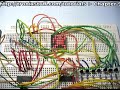
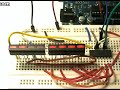
On the hardware side, it is also quite simple. If you love blinking LEDs this will make your day. It is the same as exercise 4.1, but you have another 74HC595 connected to another 8 LEDS. The clock and latch pins of both ’595s are linked together, and there is a link between pin 9 of the first register and pin 14 of the second. Below is a photo of my layout:

and a video:

Can you think of anything that has seven or eight LEDs? Hopefully this photo will refresh your memory:

Quickie – if you want to find out the remainder from a quotient, use modulo – “%”. For example:

a = 10 % 3;

returns a value of 1; as 10 divided by 3 is 3 remainder 1.

and

If you need to convert a floating-point number to an integer, it is easy. Use int();. It does not round up or down, only removes the fraction and leaves the integer.

Anyhow, now we can consider controlling these numeric displays with our arduino via the 74HC595. It is tempting to always use an LCD, but if you only need to display a few digits, or need a very high visibility, LED displays are the best option. Futhermore, they use a lot less current than a backlit LCD, and can be read from quite a distance away. A 7-segment display consists of eight LEDs arrange to form the digit eight, with a decimal point. Here is an example pinout digram:

Note that pinouts can vary, always get the data sheet if possible.

Displays can either be conmmon-anode, or common-cathode. That is, either all the LED segment anodes are common, or all the cathodes are common. Normally we will use common-cathode, as we are “sourcing” current from our shift register through a resistor (560 ohm), through the LED then to ground. If you use a common-anode, you need to “sink” current from +5v, through the resistor and LED, then into the controller IC. Now you can imagine how to display digits using this type of display – we just need to shiftout(); a byte to our shift register that is equavalent to the binary representation of the number you want to display.

Huh?

Let’s say we want to display the number ’8′ on the display. You will need to light up all the pins except for the decimal point. Unfortunately not all 7-segment displays are the same, so you need to work out which pinout is for each segment (see your data sheet) and then find the appropriate binary number to represent the pins needed, then convert that to a base-10 number to send to the display. I have created a table to make this easier:

And here is a blank one for you to print out and use: blank pin table.pdf.

Now let’s wire up one 7-segment display to our Arduino and see it work. Instead of the eight LEDs used in exercise 4.1 there is the display module. For reference the pinouts for my module were (7,6,4,2,1,9,10,5,3,8) = (a,b,c,d,e,f,g,DP, C, C) where DP is the decimal point and C is a cathode (which goes to GND). The sketch: example5p2.pdf. Note in the sketch that the decimal point is also used; it’s byte value in this example is 128. If you add 128 to the value of loopy[] in the sketch, the decimal point will be used with the numbers.

and the video:

There you go – easily done. Now it is time for you to do some work!

Exercise 5.1

Produce a circuit to count from 0 to 99 and back, using two displays and shift-registers. It isn’t that difficult, the hardware is basically the same as example 5.1 but using 7-segment displays.

You will need:

  • Your standard Arduino setup (computer, cable, Duemilanove)
  • Two 7-segment, common-cathode displays
  • Two 74HC595 shift registers
  • 16 x 560 ohm 0.25 W resistors. For use as current limiters between the LED display segments and ground
  • a breadboard and some connecting wire
  • some water

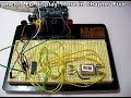
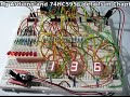
You are probably wondering how on earth to separate the digits once the count hits 10… a hint: 34 modulo 10 = 4. 34 divided by 10 = 3.4 … but 3.4 isn’t an integer. While you are thinking, here is the shot of my layout:

and the ubiquitous video:

And here is my sketch: exercise5.1.pdf

I hope you have gained more of an understanding of the possibilities available with shift registers. We will contiunue with more next week.
However, next on our agenda is some real-world hacking. This section of the chapter is more of a commentary than the usual format, but I hope you find it interesting and you receive some inspiration or ideas after reading it.

Although we have been having fun (well I have been, hopefully someone else is as well) making things on our desks or work benches, it is time to slowly enter the real world and hack something up. The other day I was in a variety store to buy some glue, and happened across a very cheap remote-control car. After noticing it had full directional control (left/right, forwards/backwards) it occured to me that we could control it with an arduino. So $9 later here it is on my desk:

Naturally I stopped everything else and had a play with it. But by crikey it was very fast:

The first thing to do would be slow this baby down. Due to the …cheapness of the product it did not have variable speed control. So the first thing to do was pull the body off to see what we had to work with:

The design is very simple, with one motor controlling the steering, and one for the speed. Luckily for me there were four wires heading to the motor from the PCB, and the were very easy to get to.

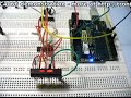
Normally we could use pulse-width modulation to slow motors down, but I don’t think we could send a PWM signal over radio control. Instead, it would be easier to reduce the voltage going to the drive motor in order to slow it down. So with the car up on blocks, the motor was set to forward with the remote and I measure the voltages across the four wires. Black and green was +3.7 in forwards, nothing in reverse, black and red was the same in reverse, and nothing forwards. Easy – just find out how much current the motor draws at full speed and then we can use Ohm’s law (voltage = current x resistance) to calculate the value of a resistor to slow it down about 70% or so.

The motor initially drew ~500 mA to start up and then reduced to ~250 mA once it got going after around one second. However, a various range of resistors from 10 to 120 ohm didn’t really seem to have much effect, and a 560 ohm knocked it out all together. So instead of trying to control speed with a hardware method, we will try with a software method… perhaps try PWM after all, or create our own.

But now, time to get the arduino interfaced with the transmitter unit. Firstly I reassembled the car, then started on the transmitter:

After cutting my finger trying to get the transmitted open, it eventually gave in and cracked open. But the effort was worth it – the control buttons were very simple rubber pads over the PCB spots:

Excellent – each controller was basically a SPDT switch, and there is plenty of space on the PCB to solder in some wires to run to the Arduino and a breadboard. The push buttons could be replaced with BC548 transistors controlled by our Arduino – the same we we controlled a relay in Chapter Three.

Next was to solder some wires from the PCB that could run to my breadboard:

The green wire is a common return, and the yellow wires are forwards, reverse, left and right. Now to set up the breadboard. Four digital out pins, connected to the base of a BC548 transistor via a 1k resistor. The emitters are connected to GND, which is also connected to the GND of the transmitter.

Just as I had finished making up the breadboard, after turning around to close a window my arm brushed the transmitter and it made a ‘crack’ noise.

My soldering had come unstuck. Oh well, it was only reverse! Time to get moving anyhow. Once again, I put the car up on blocks and uploaded the following sketch:

/*

Example 5.3

Control a toy remote control car with arduino
Chapter Five @ http://www.tronixstuff.com/tutorials
*/
int forward = 12;
int left = 9;
int right = 7;
int del = 5000;
void setup()
{
pinMode(forward, OUTPUT);
pinMode(left, OUTPUT);
pinMode(right, OUTPUT);
}
void loop()
{
digitalWrite(right, HIGH);
delay(1000);
digitalWrite(right, LOW);
delay(1000);
digitalWrite(left, HIGH);
delay(1000);
digitalWrite(left, LOW);
delay(1000);
digitalWrite(forward, HIGH);
delay(del);
digitalWrite(forward, LOW);
delay(1000);

}

It cycles throgh the three (working!) function of the car. Let’s see what happens:

That’s a good start, things are moving when we want them to move. However the car’s motors seem to be pulsing. Perhaps the resistor-transistor bridge to the arduino had something to do with that. So I threw caution to the wind and connected the digital output pins directly to the transmitter. Wow! That fixed it. The motors are going at full speed now

Using our knowledge of Arduino sketches it will be east to make this car to drive around. Let’s try that now… here is our sketch:

/*

Example 5.4

Control a toy remote control car with arduino – figure eight

Chapter Five @ http://www.tronixstuff.com/tutorials

*/

int forward = 12;

int left = 9;

int right = 7;

int del = 5000;

void setup()

{

pinMode(forward, OUTPUT);

pinMode(left, OUTPUT);

pinMode(right, OUTPUT);

}

// to make creating the car’s journey easier, here are some functions

void goleft(int runtime)

{

digitalWrite(left, HIGH);  // tell the steering to turn left

digitalWrite(forward, HIGH); // move the car forward

delay(runtime);

digitalWrite(forward, LOW);

digitalWrite(left, LOW);  // tell the steering to straighen up

}

void goright(int runtime)

{

digitalWrite(right, HIGH);  // tell the steering to turn right

digitalWrite(forward, HIGH); // move the car forward

delay(runtime);

digitalWrite(forward, LOW);

digitalWrite(right, LOW);  // tell the steering to straighen up

}

void goforward(int runtime)

// run the drive motor for “runtime” milliseconds

{

digitalWrite(forward, HIGH);  // start the drive motor forwards

delay(runtime);

digitalWrite(forward, LOW); // stop the drive motor

}

void loop()

{

goforward(1000);

goleft(1000);

goright(1000);

}

For some reason now forwards made the car go backwards. And only when I removed the GND wire from the Arduino to the breadboard. Interesting, but perhaps a problem for another day.

There we have it. Our first attempt at taking over something from the outside world and arduinising it. Now it is back to our normal readings with an exercise!

Exercise 5.2

Once again it is your turn to create something. We have discussed binary numbers, shift registers, analogue and digital inputs and outputs, creating our own functions, how to use various displays, and much more. So our task now is to build a binary quiz game. This is a device that will:

  • display a number between 0 and 255 in binary (using 8 LEDs)
  • you will turn a potentiometer (variable resistor) to select a number between 0 and 255, and this number is displayed using three 7-segment displays
  • You then press a button to lock in your answer. The game will tell you if you are correct or incorrect
  • Basically a “Binary quiz” machine of some sort!

I realise this could be a lot easier using an LCD, but that is not part of the exercise. Try and use some imagination with regards to the user interface and the difficulty of the game. At first it does sound difficult, but can be done if you think about it. At first you should make a plan, or algorithm, of how it should behave. Just write in concise instructions what you want it to do and when. Then try and break your plan down into tasks that you can offload into their own functions. Some functions may even be broken down into small functions – there is nothing wrong with that – it helps with planning and keeps everything neat and tidy. You may even find yourself writing a few test sketches, to see how a sensor works and how to integrate it into your main sketch. Then put it all together and see!

You will need: (to recreate my example below)

  • Your standard Arduino setup (computer, cable, Duemilanove)
  • Three 7-segment, common-cathode displays
  • eight LEDs (for binary number display)
  • Four 74HC595 shift registers
  • 32 x 560 ohm 0.25 W resistors. For use as current limiters between the LED display segments and ground
  • a breadboard and some connecting wire
  • 10k linear potentiometer (variable resistor)
  • some water

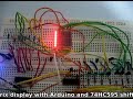
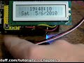
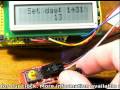
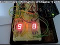
For inspiration here is a photo of my layout:


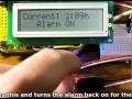
and a video of the game in operation. Upon turning on the power, the game says hello. You press the button to start the game. It will show a number in binary using the LEDs, and you select the base-10 equivalent using the potentiometer as a dial. When you select your answer, press the button  - the quiz will tell you if you are correct and show your score; or if you are incorrect, it will show you the right answer and then your score.

I have set it to only ask a few questions per game for the sake of the demonstration:

And yes – here is the sketch for my answer to the exercise: exercise 5.2.pdf

At this point we are taking a week off from the tutorials, however chapter six will be published around 21st May. But stick around – we will have two new kit reviews, some great part reviews, and a new project published in the next 7 days, so subscribe and follow us – see the top right of this web page!

High resolution images available at flickr.

If you have any questions at all please leave a comment (below). If you would like to showcase your work from this article, email a picture or a link to john at tronixstuff dot com.

You might even win a prize. Don’t forget to check out the range of gear at Little Bird Electronics!

So have fun, stay safe and see you  for our next instalment!


This is part of a series titled “Getting Started with Arduino!” – A tutorial on the Arduino microcontrollers, to be read with the book “Getting Started with Arduino” (Massimo Banzi).

The first chapter is here.

Welcome back fellow arduidans!

Hello once again to our weekly Arduino instalment. This instalment is a little early this week. This time we will be looking at getting more outputs from less pins, listening to some tunes, saying hooray to arrays, and even build a self-contained data logger!

So let’s go!

More pins from less – sounds too good to be true, doesn’t it? No, it is true and we can learn how to do this in conjunction with a special little IC, the 74HC595 Serial In/Parallel Out 8-bit Shift Register. Let’s say hello:

Before we get too carried away, we need to understand a little about bits, bytes and binary numbers.

A binary number can only uses zeros and ones to represent a value. Thus binary is also known as “base-2″, as it can only use two digits. Our most commonly used number types are base-10 (as it uses zero through to nine; hexadecimal is base-16 as it uses 0 to 9 and A to F). How can a binary number with only the use of two digits represent a larger number? It uses a lot of ones and zeros. Let’s examine a binary number, say 10101010. As this is a base-2 number, each digit represents 2 to the power of x, from x=0 onwards.

See how each digit of the binary number can represent a base-10 number. So the binary number above represents 85 in base-10 – the value 85 is the sum of the base-10 values.

Another example – 11111111 in binary equals 255 in base 10.

Now each digit in that binary number uses one ‘bit’ of memory, and eight bits make a byte. A byte is a special amount of data, as it matches perfectly with the number of output pins that the 74HC595 chip controls. (See, this wasn’t going to be a maths lesson after all). If we use our Arduino to send a number in base-10 out through a digital pin to the ’595, it will convert it to binary and set the matching output pins high or low.

So if you send the number 255 to the ’595, all of the output pins will go high. If you send it 01100110, only pins 1,2,5, and 6 will go high. Now can you imagine how this gives you extra digital output pins? The numbers between 0 and 255 can represent every possible combination of outputs on the ’595. Furthermore, each byte has a “most significant bit” and “least significant bit” – these are the left-most and right-most bits respectively.

Now to the doing part of things. Let’s look at the pinout of the 74HC595: (from Philips/NXP 74HC595 datasheet)

Pins Q0~Q7 are the output pins that we want to control. The Q7′ pin is unused, for now. ’595 pin 14 is the data pin, 12 is the latch pin and 11 is the clock pin. The data pin connects to a digital output pin on the Arduino. The latch pin is like a switch, when it is low the ’595 will accept data, when it is high, the ’595 goes deaf. The clock pin is toggled once the data has been received. So the procedure to get the data into a ’595 is this:

1) set the latch pin low (pin 12)

2) send the byte of data to the ’595 (pin 14)

3) toggle the clock pin (pin 11)

4) set the latch pin high (pin 12)

Pin 10 (reset) is connected to the +5V.

Thankfully there is a command that has parts 2 and 3 in one; you can use digitalWrite(); to take care of the latch duties. The command shiftOut(); is the key. The syntax is:

shiftout(a,b,c,d);

where:

a = the digital output pin that connects to the ’595 data pin (14);

b = the digital output pin that connects to the ’595 clock pin (11);

c can be either LSBFIRST or MSBFIRST. MSBFIRST means the ’595 will interpret the binary number from left to right; LSBFIRST will make it go right to left;

d = the actual number (0~255) that you want represented by the ’595 in binary output pins.

So if you wanted to switch on pins 1,2,5 and 6, with the rest low, you would execute the following:

digitalWrite(latchpin, LOW);

shiftOut(datapin, clockpin, MSBFIRST,102);

digitalWrite(latchpin, HIGH);

Now, what can you do with those ’595 output pins? More than you could imagine! Just remember the most current you can sink or source through each output pin is 35 milliamps.

For example:

  • an LED and a current-limiting resisor to earth… you could control many LEDs than normally possible with your Arduino;
  • an NPN transistor and something that draws more current like a motor or a larger lamp
  • an NPN transistor controlling a relay (remember?)

With two or more ’595s you can control a matrix of LEDs, 7-segment displays, and more – but that will be in the coming weeks.

For now, you have a good exercise to build familiarity with the shift-register process.

Exercise 4.1

Construct a simple circuit, that counts from 0~255 and displays the number in binary using LEDs. You will require the following:

  • Your standard Arduino setup (computer, cable, Duemilanove)
  • 8 LEDs of your choosing
  • One 74HC595 shift register
  • 8 x 560 ohm 0.25 W resistors. For use as current limiters between the LEDs and ground.
  • a breadboard and some connecting wire

The hardware is quite easy. Just remember that the anodes of the LEDs connect with the ’595, and the cathodes connect to the resistors which connect to ground. You can use the Arduino 5V and GND.

Here is what my layout looked like:

and of course a video – I have increased the speed of mine for the sake of the demonstration.

How did you go? Here is the sketch if you need some ideas – Ex 4.1

Next on the agenda today is another form of output – audio. Of course you already knew that, but until now we have not looked at (or should I say, listened to) the audio features of the Arduino system. The easiest way to get some noise is to use a piezo buzzer. An example of this is on the left hand side of the image below:

These are very simple to use and can be very loud and annoying. To get buzzing, just connect their positive lead to a digital output pin, and their negative lead to ground. Then you only have to change the digital pin to HIGH when you need a buzz. For example:

/* Example 4.1

Annoying buzzer!

CC by-sa v3.0

http://tronixstuff.wordpress.com */

void setup()

{

pinMode(12, OUTPUT);

}

void loop()

{

digitalWrite(12, HIGH);

delay(500);

digitalWrite(12, LOW);

delay(2000);

}

You won’t be subjected to a recording of it, as thankfully (!) my camera does not record audio…

However, you will want more than a buzz. Arduino has a tone(); command, which can generate a tone with a particular frequency for a duration. The syntax is:

tone(pin, frequency, duration);

where pin is the digital output pin the speaker is connected to, frequency in Hertz, duration in milliseconds. Easy!

If you omit the duration variable, the tone will be continuous, and can be stopped with notone();. Furthermore, the use of tone(); will interfere with PWM on pins 3 and 11, unless you are using an Arduino Mega.

Now, good choice for a speaker is one of those small 0.25w 8 ohm ones. My example is on the right in the photo above, taken from a musical plush toy. It has a 100 ohm resistor between the digital output pin and the speaker. Anyhow, let’s make some more annoying noise – hmm – a siren!

/* Example 4.2

Annoying siren

CC by-sa v3.0

http://tronixstuff.wordpress.com */

void setup()

{

pinMode(8, OUTPUT); // speker on pin 8

}

int del = 250; // for tone length

int lowrange = 2000; // the lowest frequency value to use

int highrange = 4000; //  the highest…

void loop()

{

// increasing tone

for (int a = lowrange; a<=highrange; a++)

{

tone (8, a, del);

}

// decreasing tone

for (int a = highrange; a>=lowrange; a–)

{

tone (8, a, del);

}

}

Phew! You can only take so much of that.

Array! Hooray? No… Arrays.

What is an array?

Let’s use an analogy from my old comp sci textbook. Firstly, you know what a variable is (you should by now). Think of this as an index card, with a piece of data written on it. For example, the number 8. Let’s get a few more index cards, and write one number on each one. 6, 7, 5, 3, 0, 9. So now you have seven pieces of data, or seven variables. They relate to each other in some way or another, and they could change, so we need a way to keep them together as a group for easier reference. So we put those cards in a small filing box, and we give that box a name, e.g. “Jenny”.

An array is that small filing box. It holds a series of variables of any type possible with arduino. To create an array, you need to define it like any other variable. For example, an array of 10 integers called jenny would be defined as:

int jenny[9];

Nine? Yes. Arrays are “zero-indexed”, which means the first element in the array is zero, and in jenny’s case, the last is 9. Just like those old HP keyboards with function keys f0~f9. Anyway. And like any other variable, you can predefine the values. For example:

int jenny[9] = {0,7,3,8,6,7,5,3,0,9};

Before we get too excited, there is a limit to how much data we can store. With the Arduino Duemilanove, we have 2 kilobytes for variables. See the hardware specifications for more information on memory and so on. To use more we would need to interface with an external RAM IC… that’s for another chapter down the track.

Now to change the contents of an array is also easy, for example

jenny[3] = 12;

will change our array to

int jenny[9] = {0,7,3,12,6,7,5,3,0,9};

You can also use variables when dealing with arrays. For example:

for (int i = 0; i<10;  i++; i<10)

{

jenny[i] = 8;

}

Will change alter our array to become

jenny[] = {8,8,8,8,8,8,8,8,8,8}

A quick way set set a lot of digital pins to output could be

int pinnumbers [] = {2,3,4,5,6,7,8,9,10,11,12,13}

for (int i= 0; i++; i<12)

{

pinMode(pinnumbers[i],OUTPUT);

}

Interesting… very interesting. Imagine if you had a large array, an analogue input sensor, a for loop, and a delay. You could make a data logger. In fact, let’s do that now.

Exercise 4.2

Build a temperature logger. It shall read the temperature once every period of time, for 24 hours. Once it has completed the measurements, it will display the values measured, the minimum, maximum, and average of the temperature data. You can set the time period to be of your own choosing. So let’s have a think about our algorithm. We will need 24 spaces to place our readings (hmm… an array?)

  • Loop around 24 times, feeding the temperature into the array, then waiting a period of time
  • Once the 24 loops have completed, calculate and display the results on an LCD and (if connected) a personal computer using the Arduino IDE serial monitor.

I know you can do it, this project is just the sum of previously-learned knowledge. If you need help, feel free to email me or post a comment at the end of this instalment.

To complete this exercise, you will need the following:

  • Your standard Arduino setup (computer, cable, Duemilanove)
  • Water (you need to stay hydrated)
  • Analog Devices TMP36 temperature sensor (Farnell part number 143-8760)
  • 1 little push button
  • 1 x 10k 0.25 W resistor. For use with the button to the arduino
  • breadboard and some connecting wire
  • one LCD display module

And off you go!

Today I decided to construct it using the Electronic Bricks for a change, and it worked out nicely.

Here is a photo of my setup:

a shot of my serial output on the personal computer:

and of course the ubiquitous video. For the purposes of the demonstration there is a much smaller delay between samples…

(The video clip below may refer to itself as exercise 4.1, this is an error. It is definitely exercise 4.2)

And here is the sketch if you would like to take a peek – Ex 4.2. High resolution photos are available in flickr.

Another week over! I’m already excited about writing the next instalment… Congratulations to all those who took part and built something useful! Please subscribe (see the top right of this page) to receive notifications of new articles.

If you have any questions at all please leave a comment (below). If you would like to showcase your work from this article, email a picture or a link to john at tronixstuff dot com.

You might even win a prize. Don’t forget to check out the range of gear at Little Bird Electronics!

So have fun, stay safe and see you soon for our next instalment!


  • Newsletter

    Sign up for the PlanetArduino Newsletter, which delivers the most popular articles via e-mail to your inbox every week. Just fill in the information below and submit.

  • Like Us on Facebook