Posts | Comments

Planet Arduino

Archive for the ‘wireless hacks’ Category

[Dave Akerman]’s interest in high-altitude projects means he is no stranger to long-range wireless communications, for which LoRa is amazingly useful. LoRa is a method of transmitting at relatively low data rates with low power over long distances.

Despite LoRa’s long range, sometimes the transmissions of a device (like a balloon’s landed payload) cannot be received directly because it is too far away, or hidden behind buildings and geography. In these cases a useful solution is [Dave]’s self-contained LoRa repeater. The repeater hardware is simple, and [Dave] says that if one has the parts on hand, it can be built in about an hour.

The device simply re-transmits any telemetry packets it receives, and all that takes is an Arduino Mini Pro and a small LoRa module. A tiny DC-DC converter, battery, and battery charger rounds out the bill of materials to create a small and self-contained unit that can be raised up on a mast, flown on a kite, or carried by a drone.

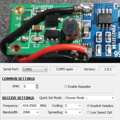
The repeater’s frequency and other settings can even be reprogrammed (using a small windows program) for maximum flexibility, making the little device invaluable when going hunting for landed payloads like the one [Dave] used to re-create a famous NASA image using a plastic model and a high-altitude balloon. Check out the details on the GitHub repository for the project and start mashing “add to cart” for parts at your favorite reseller.

Potentially, one of the great things about having a device connected to the network is that you can update it remotely. However, how do you make that happen? If you use the Arduino setup for the ESP8266 or ESP32, you might try [scottchiefbaker’s] library which promises to make the process easy.

Adding it looks to be simple. You’ll need an include, of course. If you don’t mind using port 8080 and the path /webota, you only need to call handle_webota() from your main loop. If you want to change the defaults, you’ll need to add an extra call in your setup. You also need to set up a few global variables to specify your network parameters.

The only caveat is that long delay statements in your loop can block things from working and aren’t a great idea anyway. If you have them, you can replace all your delay calls with webota_delay which will stop the system from ignoring update requests.

The code started from a different online tutorial but packaged the code up nicely for reuse. To do an update, simply navigate to the device with a web browser and use the correct port number and path. From there you can upload a new binary image taken from the Arduino IDE with the export compiled binary command.

The only concern we saw was the code didn’t appear to authenticate you at all. That means anyone could load code into your ESP. That might be ok on a private network, but on the public Internet it is surely asking for trouble. The original tutorial code did have a hardcoded user and password, but it didn’t look very useful as the password was in the clear and didn’t stop you from uploading if you knew the right URL. Dropping it from the library probably makes sense, but we would want to build some kind of meaningful security into anything we deployed.

If you have a network connection, we’ve seen the same trick done with a normal Arduino with a wireless chip. You can even do it over WiFi but using an ESP8266 which you’ll then want to be able to update, too.

It’s wasn’t so long ago that RC transmitters, at least ones worth owning, were expensive pieces of gear. Even more recently than that, the idea of an RC transmitter running an open source firmware would have been considered a pipe dream. Yet today buying cheap imported transmitters and flashing a community developed firmware (if it didn’t come with it pre-installed to begin with) is common place. It’s not much of a stretch to say we’re currently in the “Golden Age” of hobby RC transmitters.

But what if even cheap hardware running customizable software isn’t enough? What if you want to take it to the next level? In that case, [Electronoobs] has an Arduino powered RC transmitter with your name on it. But this is no scrap of protoboard with a couple of cheap joysticks on it, though he has made one of those too. The goal of this build was for it to look and perform as professional as possible while remaining within the hobbyist’s capabilities. The final product probably won’t be winning any design awards, but it’s still an impressive demonstration of what the individual hacker and maker can pull off today with the incredible technology we have access to.

So what goes into this homebrew radio control system? Inside the back panel [Electronoobs] mounted the batteries, charging module, and the voltage regulator which steps the battery voltage down to the 3.3 V required to drive the rest of the transmitter’s electronics. On the flip side there’s an Arduino Nano, an NRF24 module, and an OLED display. Finally we have an assortment of switches, buttons, potentiometers, and two very nice looking JH-D202X-R2 joysticks for user input.

As you might have guessed, building your own transmitter means building your own receiver as well. Unfortunately you won’t be able to bind your existing RC vehicles to this radio, but since the receiver side is no more complicated than another Arduino Nano and NRF24 module, it shouldn’t be hard to adapt them if you were so inclined.

Low-cost consumer RC transmitters can be something of a mixed bag. There are some surprisingly decent options out there, but it’s not a huge surprise that hackers are interested in just spinning up their own versions either.

It used to be that Web browsing was simple. You asked a server for some text, which was duly sent, and then formatted by your browser. Now a web page is as likely to be a full-blown application that is reading mail, editing text, or lots of other things and may use WebSockets to create a back channel to the server. Thanks to affordable hardware like the ESP8266 one of those things a modern web browser can do is sense and control the real world. [Acrobotic] has an interesting video about using WebSockets to allow a browser to talk to an ESP8266 web server in real time. You can see his simple demo in the video below.

Of course, you’ll use the usual language you use on the ESP8266 — [Acrobotic] uses C++ in the Arduino IDE. On the browser side you’ll use JavaScript, although that will be embedded in your C++ program which acts as a web server.

It’s as well to remember that there are several other ways you could do this. You could, for example ask for a different URL, or pass data in a query string. The problem here is that the performance would suffer as you have to establish a new connection every time. you want to transact with the server. You could also use AJAX methods but they are not as efficient either since they are primarily aimed at updating a portion of a web page dynamically. The web socket is simple enough and as you can see in the video, the performance is quite good. It also facilitates non-browser based clients that use the same service.

We’ve seen this technique used to fly a quadcopter. WebSockets have been around for a while, so your browser should support them. If it doesn’t, though, you can always use this hack — at least in one direction.

A few months back we first brought word of the progress being made in unlocking the SMART Response XE, an ATmega128RFA powered handheld computer that allowed teachers to create an interactive curriculum in the days before all the kids got Chromebooks. Featuring 2.4 Ghz wireless communication, a 384×160 LCD, and a full QWERTY keyboard, schools paid around $100 each for them 2010. Now selling for as little as $5 on eBay, these Arduino-compatible devices only need a little coaxing and an external programmer to get your own code running.

The previous post inspired [Larry Bank] to try his hand at hacking the SMART Response XE, and so far he’s made some very impressive progress. Not only has he come up with his own support library, but he’s also created a way to upload Arduino code to the devices through their integrated 802.15.4 radio. With his setup, you no longer need to open the SMART Response XE and attach a programmer, making it much easier to test and deploy software.

[Larry] has written up a very detailed account of his development process, and goes through the trouble of including his ideas that didn’t work. Getting reliable communication between two of these classroom gadgets proved a bit tricky, and it took a bit of circling around until he hit on a protocol that worked.

The trick is that you need to use one SMART Response XE attached to your computer as a “hub” to upload code to other XEs. But given how cheap they are this isn’t that big of a deal, especially considering the boost in productivity it will net you. [Larry] added a 5 x 2 female header to his “hub” XE so he could close the device back up, and also added a physical power switch. In the video after the break, you can see a demonstration of the setup sending a simple program to a nearby XE.

Between this wireless bootloader and the Arduboy compatibility covered previously, we’d suggest you get your SMART Response XE now. We wouldn’t be surprised if the prices of these things start going up like they did with the IM-ME.

Cheap second-hand hardware is usually a fertile ground for hacking, and it looks like these digital classroom aids are no exception. [is0-mick] writes in to tell us how he managed to hack one of these devices, a Smart Reponse XE, into an Arduboy compatible game system. As it turns out, this particular gadget is powered by an ATmega128RFA, which is essentially an Arduino-compatible AVR microcontroller with a 2.4GHz RF transceiver tacked on. This makes it an extremely interesting platform for hacking, especially since they are going for as little as $3 USD on eBay.

There’s no USB-Serial converter built into the Smart Response XE, so you’ll need to provide your own external programmer to flash the device. But luckily there’s a labeled ISP connector right on the board which makes it pretty straightforward to get everything wired up.

Of course, getting the hardware working was slightly more complicated than just flashing an Arduino Sketch onto the thing. [is0-mick] has provided his bootloader and modified libraries to get the device’s QWERTY keyboard and ST7586S controlled 384×160 LCD working.

Playing games is fun, but when his friend [en4rab] sent him the Smart Response XE to fiddle with, the goal was actually to turn them into cheap 2.4 GHz analyzers similar to what was done with the IM-ME. It seems they’re well on their way, and [is0-mick] invites anyone who might be interested in filling in some of the blanks on the RF side to get involved.

If you are interested in deploying LoRa — the low power long-range wireless technology — you might enjoy [Rui Santos’] project and video about using the ESP32 with the Arduino IDE to implement LoRa. You can see the video below. He uses the RFM95 transceivers with a breakout board, so even if you want to use a different processor, you’ll still find a lot of good information.

In fact, the video is just background on LoRa that doesn’t change regardless of the host computer you are using. Once you have all the parts, getting it to work is fairly simple. There’s a LoRa library by [Sandeep Mistry] that knows how to do most of the work.

Although the project uses an RFM95, it can also work with similar modules such as the RFM96W or RFM98W. There are also ESP32 modules that have compatible transceivers onboard.

This is one of those projects that probably isn’t useful all by itself, but it can really help you get over that hump you always experience when you start using something new. Once you have the demo set up, it should be easy to mutate it into what you really need.

We’ve been talking about LoRa a lot lately. We’ve even seen it commanding drones.

When [Im-pro] wants a display, he wants it to spin.  So he built a persistence of vision (POV) display capable of showing a 12-bit color image of 131 x 131 pixels at 16 frames per second. You can see a video about the project below, but don’t worry, you can view it on your normal monitor.

The project starts with a Java-based screen capture on a PC. Data goes to the display wirelessly to an ESP8266. However, the actual display drive is done by an FPGA that drives the motor, reads a hall effect index sensor, and lights the LEDs.

Perhaps the most interesting part of the project is the FPGA-based mapping of the rectangular coordinates of the incoming video to the polar coordinates required by the display. There are 4 arms of LEDs or “wings” and a 3D printed structure that is all included in the post.

The FPGA is a Cmod S6 which is a breakout board for a Xilinx Spartan 6 with more than enough horsepower to handle the workload. There are also custom PCBs involved, so when you think about it, it is a fairly wide-ranging project. Java software, ESP8266 software, FPGA configurations, a 3D-printed design, and PCB layouts. If you want something simple to tackle that has a bit of everything in it, this might be your next project.

Most of the POV displays we see don’t have this kind of color-depth and resolution. We’ve seen displays built around fans. Our favorite, though, is the dog speedometer.

Pools have come a long way. It used to be you had a pump and if you were lucky it had a mechanical timer switch on it. That was it. Now you have digital controllers and spa jets and heaters. You can even get them that connect to your home automation system. If your pool isn’t new enough to do that already, you can get a range of add-on accessories. For a price. [Rob] paid $500 to get a remote for his pool. It wasn’t even WiFi, just a simple RF remote. In 3 years, the transmitter had burned out ($300 to replace) and he decided he had enough. For $20, [Rob] added MQTT control and monitoring to his pool using an ESP8266. You can see the video description of the project below.

Naturally, the instructions are a bit specific to the Pentair system he has. However, it isn’t as specialized as you might think. The project relies on the connection for a wired “spa-side remote” that most modern pool systems support. The electrical connections for these aren’t quite standard, but they are all very similar, so you have a good chance of reproducing this for your setup assuming you have a connection for one of these wired remotes.

The remote has a few buttons and LED for status. The LED reacts differently depending on the pool’s current mode, so connecting there not only gives you control but also allows you to provide some limited status. It isn’t going to let you monitor pump currents or anything exotic, but it is a simple place to gain access. Using the Arduino pulse input function makes it easy to sense if the LED is on, off, or blinking. Another sensor reads the water temperature. The controller makes it available, but it isn’t simple to read, so the project just reads the raw sensor voltage from the existing thermistor and computes the temperature.

[Ron] does a nice job of explaining some basic concepts like using opto-isolators. However, the real value to the video is the easy way to interface to the existing controller. A little configuration into Home Automation rounds out the project.

If you have an older system, you might like to see more of a pool system rebuild. If you are interested in controlling the pool chemistry, we’ve seen that before, too.

Some of the best hacks are the ones which seem perfectly obvious in hindsight; a solution to the problem that’s so elegant, you wonder how it never occurred to you before. Of course we also love the hacks that are so complex your eyes start to water, but it’s nice to have a balance. This one, sent in by [Eduardo Zola] is definitely in the former group.

In the video after the break, [Eduardo] demonstrates his extremely simple setup for using ultrasonic transducers for one-way data communication. Powered by a pair of Arduinos and using transducers salvaged from the extremely popular HC-SR04 module, there’s a good chance a lot of readers can recreate this one on their own bench with what they’ve got lying around. In this example he’s sending strings of text from one computer to another, but with a little imagination this can be used for all sorts of projects.

For the transmitter, the ultrasonic transducer is simply tied to one of the digital pins on the Arduino. The receiver is a bit more complex, requiring a LM386 amplifier and LM393 comparator to create a clean signal for the second Arduino to read.

But how does it work? Looking through the source code for the transmitter and receiver, we can see it’s about as basic as it gets. The transmitter Arduino breaks down a given string into individual characters, and then further converts the ASCII to eight binary bits. These bits are sent out as tones, and are picked up on the receiving end. Once the receiver has collected a decent chunk of tones, it works through them and turns the binary values back into ASCII characters which get dumped over serial. It’s slow, but it’s simple.

If you’re looking for something a bit more robust, check out this guide on using GNU Radio with ultrasonics.


  • Newsletter

    Sign up for the PlanetArduino Newsletter, which delivers the most popular articles via e-mail to your inbox every week. Just fill in the information below and submit.

  • Like Us on Facebook