Posts | Comments

Planet Arduino

Archive for the ‘3d printed’ Category

Light painting is a technique which allows you to “draw” on a photograph by moving a light past the camera during a long exposure shot. While it can be difficult to master, light painting allows for some incredible effects such as text and images that appear to be hovering in mid-air. Think of it like a very slow but much cooler version of an augmented reality app.

[Reven] recently wrote in to tell us about the Arduino light painter he put together, and while DIY (and even commercial) light painting gear isn’t exactly new at this point, we think he’s raised the bar a bit with his design. With the addition of a slick 3D printed enclosure and on-board display and menu system, his light painter looks exceptionally professional for being built out of hardware he had on hand.

On his blog, [Reven] has done a phenomenal job of documenting the build from start to finish. Not only does he include a detailed Bill of Materials and the STL files so you can build your own version of his light painter, he walks the reader though his design process and explains why he did the things he did. Even if you aren’t interested in building a light painter, there’s almost certainly something of interest for anyone who’s ever looked at a pile of parts on their workbench and wondered how they were going to turn it into a functioning device.

Powered by an Arduino Uno, the light painter provides a user interface on a 16×2 LCD which allows control over not only the brightness of the WS2812 LED strips but selecting and loading different images from the micro SD card. The case was designed in FreeCAD, and while [Reven] mentions there are a number of issues which could be improved, satisfies all his design goals.

We covered the original Adafruit project that [Reven] based his code all the way back in 2013, though there’s certainly been more modern interpretations of the idea since then.

If the term “3D printed weather station” makes you think of a printed enclosure for off-the-shelf sensors, don’t feel bad. We thought the same thing when we first read the message [Rob Ward] sent in about his latest project. Surely he couldn’t mean that he actually printed all the principal parts of a serious weather station setup, such as the wind vane, anemometer, or rain gauge?

Except, on closer inspection, that’s exactly what he did. Every part of the weather station is designed in OpenSCAD, printed out, and infused with various vitamins to turn them into functional pieces of hardware. Interestingly enough, most of the magic is done with simple reed switches and magnets.

For example, the wind vane uses eight reed switches and an embedded magnet to communicate the current wind direction to the Arduino Uno which handles the user interface. Wind speed, on the other hand, it done with a single reed switch as it just needs to count rotations to calculate speed.

[Rob] did “cheat” by using an off-the-shelf barometric pressure sensor, but we’ll give him a pass for that one. Unless somebody wants to hit the tip line with a design for a printable barometer, we’ll consider this the high water mark in printable weather stations.

This isn’t the first time we’ve seen a DIY anemometer or rain gauge, of varying degrees of complexity. But the clean look of the final version, completely open nature of the OpenSCAD source, and the low part count make this an extremely compelling option for anyone looking to up their home forecasting game.

We’re big fans of the impractical around here at Hackaday. Sure there’s a certain appeal to coming up with the most efficient method to accomplish your goal, the method that does exactly what it needs to do without any superfluous elements. But it’s just not as much fun. If at least one person doesn’t ask “But why?”, then you probably left something on the table, design wise.

So when we saw this delightfully complex clock designed by [Tucker Shannon], we instantly fell in love. Powered by an Arduino, the clock uses an articulated arm with a UV LED to write out the current time on a piece of glow-in-the-dark material. The time doesn’t stay up for long depending on the lighting in the room, but at least it only takes a second or two to write out once you press the button.

Things are pretty straightforward inside the 3D printed case. There’s an Arduino coupled with an RTC module to keep the time, which is connected to the two standard hobby servos mounted in the front panel. A UV LED and simple push button round out the rest of the Bill of Materials. The source code is provided, so you won’t have to figure out the kinematics involved in getting the two servos to play nicely together if you want to try this one at home.

We’ve seen many clocks powered by Arduinos over the years, occasionally they even have hands. But few can boast their own robotic arm.

Hope you weren’t looking forward to a night of sleep untroubled by nightmares. Doing his part to make sure  Lovecraftian mechanized horrors have lease in your subconscious, [Paul-Louis Ageneau] has recently unleashed the horror that is Eyepot upon an unsuspecting world. This Cycloptic four legged robotic teapot takes inspiration from an enemy in the game Alice: Madness Returns, and seems to exist for no reason other than to creep people out.

Even if you aren’t physically manifesting nightmares, there’s plenty to learn from this project. [Paul-Louis Ageneau] has done a fantastic job of documenting the build, from the OpenSCAD-designed 3D printed components to the Raspberry Pi Zero and Arduino Pro Mini combo that control the eight servos in the legs. If you want to play along at home all the information and code is here, though feel free to skip the whole teapot with an eyeball thing.

A second post explains how the code is written for both the Arduino and Pi, making for some very illuminating reading. A Python script on the Pi breaks down the kinematics and passes on the appropriate servo angles to the Arduino over a serial link. Combined with a web interface for control and a stream from the teapot’s Raspberry Pi Camera module, and you’ve got the makings of the world’s creepiest telepresence robot. We’d love to see this one stomping up and down a boardroom table.

Seems we are on a roll recently with creepy robot pals. Seeing a collaboration between Eyepot and JARVIS might be too much for us to handle. Though we have a pretty good idea how we’d want to control them.


After you’ve taken a moment to ponder the turn of phrase used in the title, take a look at this scratch-built robotic vacuum created by [theking3737]. The entire body of the vacuum was 3D printed, and all of the internal electronics are off-the-shelf modular components. We can’t say how well it stacks up against the commercial equivalents from iRobot and the like, but it doesn’t look like it would be too hard to build one yourself to find out.

The body of this rather concerned-looking robot was printed on a DMS DP5 printer, which is a neat trick as it only has a build platform of 200 mm x 200 mm. Once all the pieces were printed, a 3D pen was used to “weld” the sections together. The final result looks a bit rough, but should give a bond that’s just as strong as the printed parts themselves.

The robot has four sets of ultrasonic range finders to detect walls and obstacles, though probably not in the positions you would expect. The right side of the robot has two sets of sensors, while the left side only gets one. We aren’t sure the reasoning behind the asymmetrical layout, but presumably the machine prefers making right turns.

Control is provided by an Arduino Mega and the ever-reliable HC-05 Bluetooth module. A companion Android application was written which allows configuring the robot without having to plug into the Arduino every time you want to tweak a setting.

We can’t say we’ve seen that many DIY robotic vacuums here at Hackaday, but we’ve certainly featured our fair share of hacks for the commercially available models.

While the vast majority of us are content to plod along with the squishy chiclet keyboards on our laptops, or the cheapest USB membrane keyboard we could find on Amazon, there’s a special breed out there who demand something more. To them, nothing beats a good old-fashioned mechanical keyboard, where each key-press sounds like a footfall of Zeus himself. They are truly the “Chad” of the input device world.

But what if even the most high end of mechanical keyboards doesn’t quench your thirst for spring-loaded perfection? In that case, the only thing left to do is design and build your own. [Matthew Cordier] recently unveiled the custom mechanical keyboard he’s been working on, and to say it’s an elegant piece of engineering is something of an understatement. It may even better inside than it does on the outside.

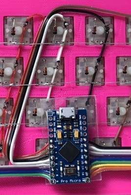
The keyboard, which he is calling z.48, is based around the Arduino Pro Micro running a firmware generated on kbfirmware.com, and features some absolutely fantastic hand-wiring. No PCBs here, just a rainbow assortment of wire and the patience of a Buddhist monk. The particularly attentive reader may notice that [Matthew] used his soldering iron to melt away the insulation on his wires where they meet up with the keys, giving the final wiring job a very clean look.

Speaking of the keys, they are Gateron switches with DSA Hana caps. If none of those words mean anything to you, don’t worry. We’re through the Looking Glass and into the world of the keyboard aficionado now.

Finally, the case itself is printed on a CR-10 with a 0.3 mm nozzle and 0.2 mm layers giving it a very fine finish. At 70% infill, we imagine it’s got a good deal of heft as well. [Matthew] mentions that a production case and a PCB are in the cards for the future as he hopes to do a small commercial run of these boards. In the meantime we can all bask in the glory of what passes for a prototype in his world.

We’ve seen some exceptionally impressive mechanical keyboards over the years, including the occasional oddity like the fully 3D printed one and even one that inexplicably moves around. But this build by [Matthew] has to be one of the most elegant we’ve ever come across.

[Thanks to DarkSim905 for the tip]

A delightful version of a clever one-dimensional game has been made by [Critters] which he calls TWANG! because the joystick is made from a spring doorstop with an accelerometer in the tip. The game itself is played out on an RGB LED strip. As a result, the game world, the player, goal, and enemies are all represented on a single line of LEDs.

How can a dungeon crawler game be represented in 1D, and how is this unusual game played? The goal is for the player (a green dot) to reach the goal (a blue dot) to advance to the next level. Making this more difficult are enemies (red dots) which move in different ways. The joystick is moved left or right to advance the player’s blue dot left or right, and the player can attack with a “twang” motion of the joystick, which eliminates nearby enemies. By playing with brightness and color, a surprising amount of gameplay can be jammed into a one-dimensional display!

Code for TWANG! is on github and models for 3D printing the physical pieces are on Thingiverse. The video (embedded below) focuses mainly on the development process, but does have the gameplay elements explained as well and demonstrates some slick animations and sharp feedback.

Using a spring doorstop as a controller is neat as heck as well as intuitive, but possibly not quite as intuitive as using an actual car as a video game controller.

If there’s one thing that Hollywood knows about hackers, it’s that they absolutely love data visualizations. Sometimes it’s projected on a big wall (Hackers, WarGames), other times it’s gibberish until the plot says otherwise (Sneakers, The Matrix). But no matter what, it has to look cool. No hacker worth his or her salt can possibly work unless they’ve got an evolving Venn diagram or spectral waterfall running somewhere in the background.

Inspired by Hollywood portrayals, specifically one featured in Avengers: Age of Ultron, [Zack Akil] decided it was time to secure his place in the pantheon of hacker wall visualizations. But not content to just show meaningless nonsense on his wall, he set out to create something that was at least showing actual data.

[Zack] created a neural network to work through multi-label classification data in Python using the scikit-learn machine learning suite. The code takes the values from the neutral network training algorithm and converts them to RGB colors by way of an Arduino. Each “node” in the neutral network is 3D printed in translucent filament, and fitted with an RGB LED module. These modules are then connected to each other via side-glow fiber optic tubes, so that the colors within the tubes are mixed depending on the colors of the nodes they are attached to. This allows for a very organic “growing” effect, as colors move through the network node-by-node.

In the end this particular visualization doesn’t really mean anything; the data it’s working on only exists for the purposes of the visualization itself. But [Zack] succeeded in creating a practical visualization of machine learning, and if you’re the kind of person who needs to keep tabs on learning algorithms, some variation of this design may be just what you’re looking for.

If AI isn’t your thing but you still want a wall of RGB LEDs, maybe you can use this phased array antenna visualizer instead. If you’re really hip, maybe you’ll go the analog route and put a big gauge on the wall.


Filed under: Arduino Hacks, led hacks

A personal bartender is hard to come by these days. What has the world come to when a maker has to build their own? [Pierre Charlier] can lend you a helping hand vis-à-vis with HardWino, an open-source cocktail maker.

The auto-bar is housed on a six-slot, rotating beverage holder, controlled by an Arduino Mega and accepts drink orders via a TFT screen. Stepper motors and L298 driver boards are supported on 3D printed parts and powered by a standard 12V DC jack. Assembling HardWino is a little involved, so [Charlier]  has provided a thorough step-by-step process in the video after the break.

[Charlier] has also kindly included his Arduino code to further facilitate your happy hour. The best part? This is isn’t even the final product; and yet — this functional prototype can already turn the tables on a long day. Whatever your beverage of choice, make sure it stays as hot or cool as you want with the help of this handy coaster.


Filed under: 3d Printer hacks, Arduino Hacks


  • Newsletter

    Sign up for the PlanetArduino Newsletter, which delivers the most popular articles via e-mail to your inbox every week. Just fill in the information below and submit.

  • Like Us on Facebook