Posts | Comments

Planet Arduino

Archive for the ‘micro’ Category

Almost all modern video games require either a gamepad or a keyboard and mouse, which means that they’re inaccessible to many people with disabilities that affect manual dexterity. Bob Hammell’s voice-enabled controller lets some of those people experience the joy of video games.

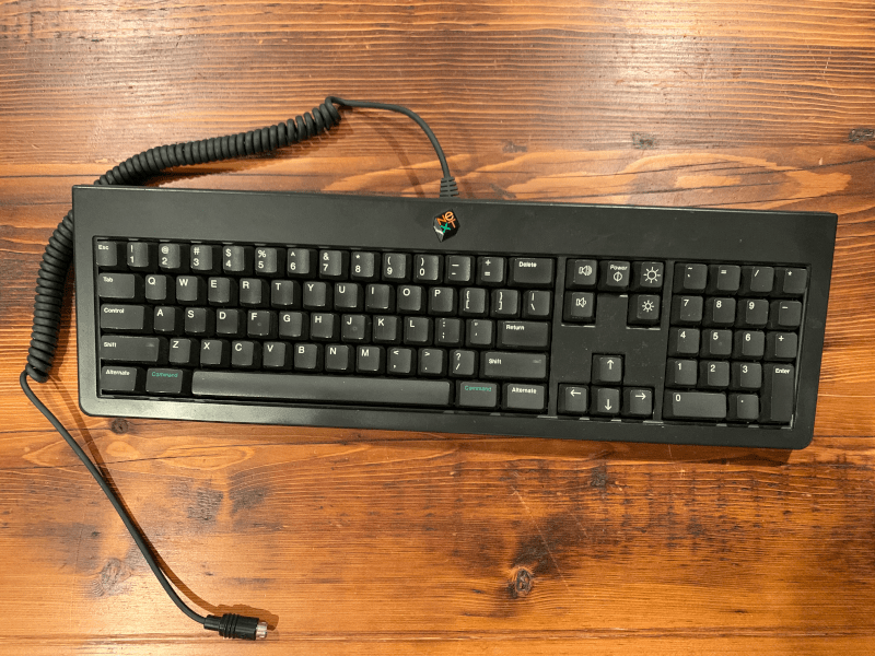
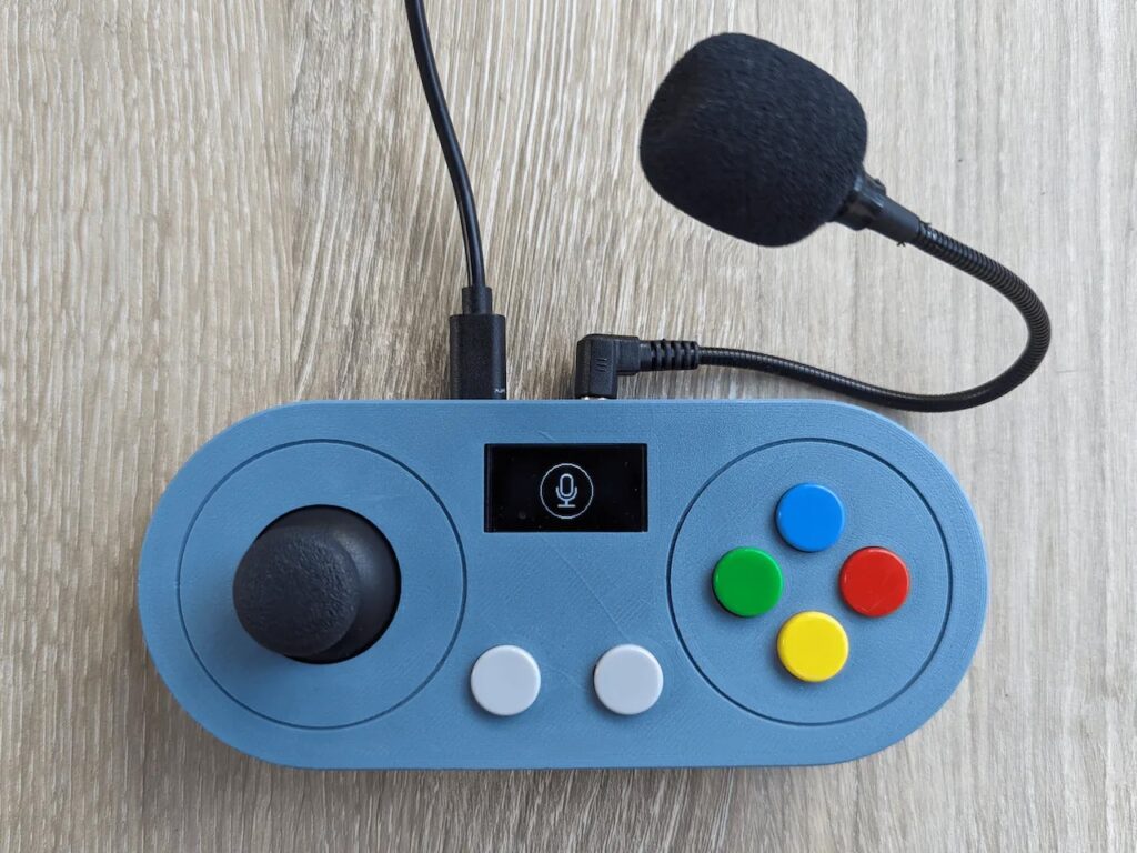
This is a simplified video game controller with a minimal number of physical buttons, but with special voice-activated virtual buttons to make up the difference. The gamepad only has six physical buttons, plus an analog joystick. That makes it much easier to handle than a typical modern controller, which might have a dozen buttons and two joysticks. If the player has the ability, they can utilize the physical controls and then speak commands to activate the game functions not covered by those buttons.

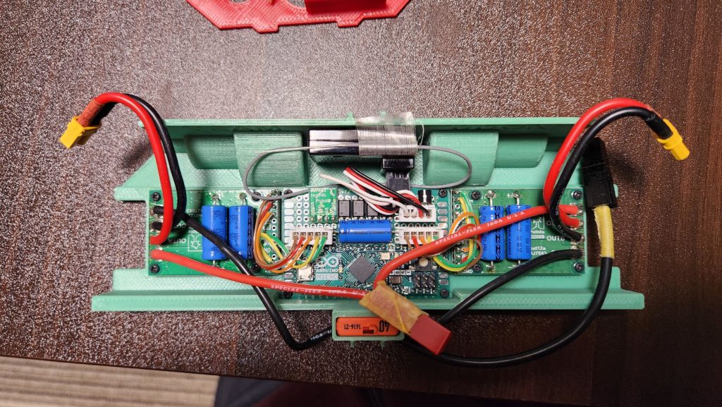
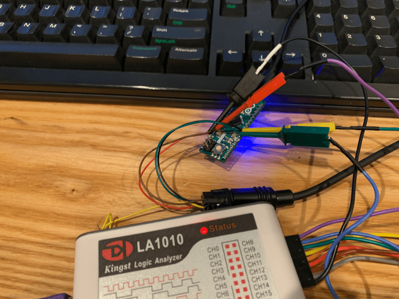
The controller’s brain is an Arduino Micro board, which Hammell selected because it can be configured to show up as a standard USB HID gamepad or keyboard when connected to a PC. The physical controls are an Adafruit analog two-axis joystick and tactile switches. An Adafruit 1.3″ OLED screen displays information, including the status of the voice activation.

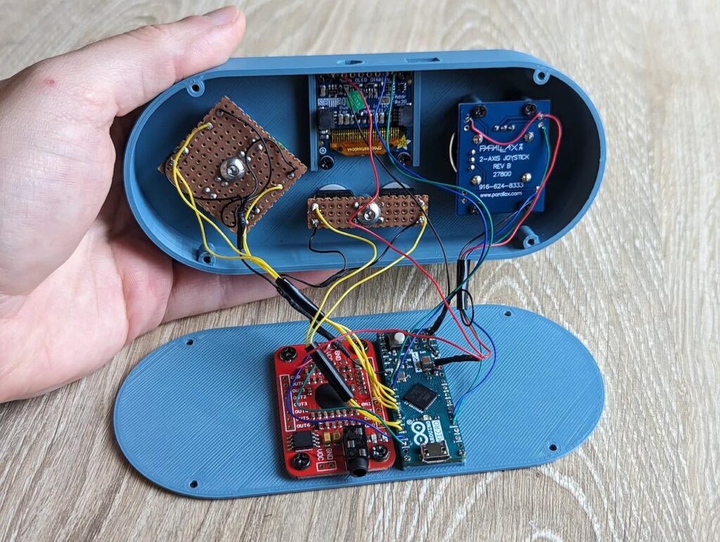
An Elechouse V3 Voice Recognition Module performs the voice recognition and it can understand up to 80 different commands. When it recognizes a command, like “menu,” it tells the Arduino to send the corresponding virtual button press to the connected computer. It takes time for a person to speak a command, so those are best suited to functions that players don’t use very often.

If you know someone that would benefit from a controller like this, Hammell posted a full tutorial and all of the necessary files to Hackster.io so you can build your own.

The post Voice-enabled controller makes video games more accessible appeared first on Arduino Blog.

For fans of Harry Potter, Hogwarts Legacy is a dream game. It drops you into the Potterverse where you can become a wizard, casting spells and riding brooms to your heart’s content. It is a very immersive game, but you lose some of that immersion when you realize you’re actually just pushing buttons on a gamepad. That’s why YouTuber ‘That’s So Mo’ built a custom Hogwarts Legacy controller on a replica Nimbus 2000 broom.

The broom itself is the property of Mo’s friend. It is a very expensive prop replica that looks just like the Nimbus 2000 from the films. Mo couldn’t risk any damage to that, so he attached all of the components to a block of packing foam that can slide on and off the broom handle. Those components include an Arduino, an accelerometer, and an ultrasonic distance sensor.

Thanks to its onboard ATmega32U4 microcontroller, the Arduino is configurable to appear as a USB HID gamepad when connected to a PC. The button presses it sends depend on the orientation of the broom stick and the position of the rider’s body. The accelerometer monitors orientation while the ultrasonic sensor checks the distance to the rider’s torso. So if the rider tucks in close to the Nimbus 2000, the in-game avatar will speed up. If the rider leans right, the avatar will turn right.

With this controller, Mo can play like he’s really riding a broom — at least for as long as his friend lets him borrow the Nimbus 2000!

The post Building a custom broom controller for Hogwarts Legacy appeared first on Arduino Blog.

While it is easier now than ever before, getting into robotics is still daunting. In the past, aspiring roboticists were limited by budget and inaccessible technology. But today the challenge is an overwhelming abundance of different options. It is hard to know where to start, which is why Saul designed a set of easy-to-build and affordable robots called Bolt Bots.

There are currently five different Bolt Bot versions to suit different applications and you can build all of them with the same set of hardware. Once you finish one, you can repurpose the components to build another. The current designs include a large four-leg walker (V1), a tiny four-leg walker (V2), a robot arm (V3), a car (V4), and a hanging plotter that can draw (V5). They all have a shared designed language and utilize 3D-printed mechanical parts with off-the-shelf fasteners.

Every robot has an Arduino Micro board paired with an nRF24L01 radio transceiver module for control. Users can take advantage of existing RC transmitters or build a remote also designed by Saul. The other components include servo motors, an 18650 lithium battery, and miscellaneous parts likes wires and screws. Some of the Bolt Bots require different servo motors, like continuous-rotation and mini 1.8g models, but most of them are standard 9g hobby servo motors.

Because there are five Bolt Bot variations that use the same components, this is an awesome ecosystem for getting started in robotics on a budget — especially for kids and teens.

The post Bolt Bots are perfect for aspiring roboticists appeared first on Arduino Blog.

The simplest MIDI (Musical Instrument Digital Interface) input devices use good ol’ fashioned buttons: push a button and the device sends a MIDI message to trigger a specific note. But that control scheme doesn’t replicate the flexibility of a real instrument very well, because a standard button is a binary mechanism. To introduce more range, Xavier Dumont developed this breath-controlled MIDI device.

This looks like a cross between a flute, an ocarina, and an old cell phone. The front face has 35 buttons to trigger specific notes. But there are two ways for the player to gain almost analog control over the output: a mouthpiece with a breath sensor and a linear touch sensor. The breath sensor lets the player control the intensity of a note by blowing into the mouthpiece like a wind instrument. The linear touch sensor, mounted on the bottom of the device, lets the user bend the pitch of the notes with their thumb.

Inside the 3D-printed enclosure is a custom PCB. Almost every component mounts directly onto that board. The exception is the touch sensor, which connects to the PCB through a jumper cable. An Arduino Micro monitors the keypad matrix, the touch sensor, and the breath sensor. It outputs MIDI messages to a computer connected via USB. There is a TFT screen for the control interface, which lets the user change modes, switch octaves, and tweak settings

The post An open-source, breath-controlled MIDI device appeared first on Arduino Blog.

While the majority of makers are unable to afford the fancy equipment and components that go into modern state-of-the-art battle robots, there do exist lesser-known tournaments for more DIY designs, including sumo robot battles. Instructables user noclaf8810373’s design incorporates all of the high-powered components one would expect to find, along with an innovative defense mechanism.

Construction of the robot began by 3D printing nearly everything from ABS filament due to its strength and resistance to high temperatures, whereas nylon was used in the gear. Once cleaned up, a series of strong magnets were set into both the front blade and undercarriage to assist in preventing the robot from flipping over due to an opposing robot. Internally, a pair of motors drive the wheels through several gears for increased torque, and they are both controlled by an Arduino Micro. In this case, the microcontroller’s role is to take incoming data from the radio transmitter, convert it into commands, and set the motors accordingly.

After assembling the electronic components, including the Arduino, motor drivers, and large capacitors onto a piece of perfboard, they were securely fastened inside the robot’s interior compartment. To see more about the build process, you can check out the project’s write-up here on Instructables.

The post This 3D-printed robot is made for sumo battle tournaments appeared first on Arduino Blog.

As part of his ongoing PorscheKart project, YouTuber Wesley Kagan wanted a better way to steer his V12 custom-built race car, as the previous wheel was simply a mechanical linkage to the front steering. Instead, this new version would closely mimic the layout and functionality of an actual Formula 1 wheel, complete with all of the buttons, dials, switches, and the central screen.

The base of the wheel was formed from a laser-cut sheet of aluminum while the surrounding grips were painstakingly 3D-printed out of TPU filament. For the electronics, Kagan decided to use a pair of Arduino Micros, which were split between handling button inputs and driving the display, while an Arduino Mega 2560 gathers sensor data and sends it as a string to the two boards. Because of the limited number of pins, he wired each of the three rotary switches’ output pins to a differently valued resistor, thereby letting the analog input on the Micro know which position is selected by the incoming voltage.

The final steps of building this upgraded steering included connecting the 3.5” LCD screen to one of the Arduino Micro boards and wiring everything together with the help of a couple harnesses to minimize the mess. However, creating the graphics program proved to be a challenge due to the limited space in ROM for storing all of the draw function calls, which is why Kagan plans on eventually swapping it out for a static image that has the values filled-in. To see more about the project, you can watch his build log video below and read this blog post.

The post Wesley Kagan’s PorscheKart project returns with a new Arduino-powered F1 steering wheel appeared first on Arduino Blog.

Working with vintage computer technology can feel a bit like the digital equivalent of archeology. Documentation is often limited or altogether absent today — if it was ever even public in the first place. So you end up reverse engineering a device’s functionality through meticulous inspection and analysis. Spencer Nelson has a vintage NeXT keyboard from the ’80s and wanted to get it working with modern computers via USB. To make that happen, he reverse engineered the protocol and used an Arduino as an adapter.

NeXT was a computer company founded by Steve Jobs in the ’80s, in the period after he left Apple. A little over ten years later, Apple bought NeXT and Jobs rejoined the company. NeXT only released a few computers, but they are noteworthy and desirable to collectors. This particular keyboard is from 1988 and worked with the first generation NeXT Computer. Unlike modern keyboards that share the USB protocol, keyboards from this era utilized proprietary protocols. This particular model had an enigmatic protocol that Nelson became obsessed with deciphering.

Nelson started with an Arduino Micro with the intention of using an existing library. But that resulted in unpredictable and jumbled text. After inspecting the keyboard’s output signal with both an oscilloscope and a logic analyzer, Nelson determined that the keyboard protocol worked at an unusual 52.74 microsecond pulse width that the library didn’t account for. It turns out that that was the result of NeXT using a cheap 455 kHz resonator intended for AM radios. Every 24 ticks of that resonator, it would send a data bit (18,958 hertz equals once pulse every 52.74 microseconds).

With this information in hand, Nelson was able to create his own Arduino sketch to analyze the signal coming from the NeXT keyboard. It can output the text via the serial console, but it is also possible to configure an Arduino as a USB HID to output the text to any modern computer.

The post Reverse engineering an ’80s NeXT keyboard appeared first on Arduino Blog.

In circumstances where extreme precision is required when dealing with the movement of microscopic amounts of liquids, such as lab-on-a-chip (LoC) and organs-on-a-chip (OoC) systems, obtaining a pump that is both cheap and accurate is nearly impossible since they often cost several thousands of dollars to procure or are too bulky. To combat this problem, a team from the Singapore University of Technology and Design Soft Fluidics Lab created a custom solution that can be fabricated with off-the-shelf 3D printers. 

The device they came up with relies on a single Arduino Micro to control the flowrate of the pump by adjusting the speed of the connected motor. There is also an optional OLED that can be added that lets users see the exact flowrate which has been selected. Altogether, this DIY pump system is capable of moving a mere 0.02 microliters up to 727.3 microliters per minute with a footprint of around 20mm by 50mm. Perhaps best of all, this project can be easily sent as a kit and built onsite with incredible speed, further reducing the cost to use it.

For more details on this 3D-printed peristaltic pump system, you can read the team’s research paper.

(Image credit: T. Ching et al.)

The post This 3D-printed, Arduino-controlled kit makes microfluidic pumps more accessible appeared first on Arduino Blog.

Mounts in the video game Final Fantasy XIV act like how cars or horses do in our world since they allow players to travel around the map much faster than would otherwise be possible. But even better, mounts are ways to express personality and have some fun, which is especially evident with the infamous “Fatter Cat” mount, as it got so widely beloved that Square Enix, the game’s publisher, decided to start selling a plushie version of it in their store. 

With his own Fatter Cat cushion, FFXIV modder Louis Hamilton (SuperLouis64 on YouTube) decided to add some extra functionality by attaching both a touch sensor and a passive infrared module that lets it sense when someone has sat on it. This in turn causes an Arduino Micro board to send out a keystroke that activates a macro in the game, thus causing the Fatter Cat mount to appear. 

You can watch SuperLouis64’s video below for a short demonstration of how this fun system works.

The post Converting a Fat Cat cushion into a controller for Final Fantasy XIV appeared first on Arduino Blog.

This year for Halloween, Quint BUILDs wanted to make something special for his daughter’s costume. Quint’s idea was to design and fabricate a pair of mechatronic dragon wings that can mount to a user’s back and move in three different modes by utilizing a set of pneumatic air cylinders. 

The prototype began as a single air cylinder connected to a relay that was, in turn, controlled by a single Arduino Micro and button. This way, Quint could finely tune the timings and pressures required for the device. After 3D printing a simple controller, machining a few aluminum plates, and welding it all together into a second prototype, it was time to experiment with programming more complex movements. 

Three pneumatic cylinders were used to create a couple axes of motion. First, the larger base cylinder moves a central piston vertically, thus extending and retracting them outwards. Each wing can flap independently through the use of two smaller pistons and linkages. Finally, pressurized air is provided by a compressed CO2 canister. These actuators are each controlled by a dedicated relay module that’s connected to an Arduino Uno.

Whenever one of the three buttons on the controller are pressed, a subroutine for the specified movement is executed. This could include fluttering the wings a couple of times, extending them outwards, and even performing a more complicated flapping motion. 

To see how this project was built in more detail, you can check out Quint’s write-up here on Instructables.

The post Scale up your dragon costume with wings that extend, flap and retract appeared first on Arduino Blog.


  • Newsletter

    Sign up for the PlanetArduino Newsletter, which delivers the most popular articles via e-mail to your inbox every week. Just fill in the information below and submit.

  • Like Us on Facebook