06
This is a guest post from Surrogate, a team of developers building games that people play in real-life over the internet.
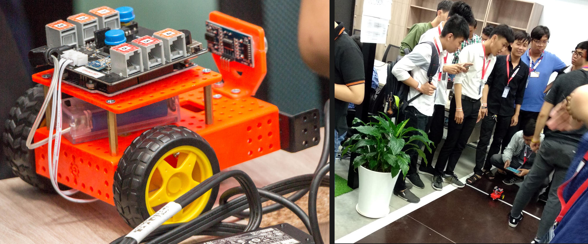
We introduced this concept last year, and have launched three games so far. Our final game of 2019 was SumoBots Battle Royale — where players from anywhere in the world can fight real robots in a battle royale-style arena. The aim of the project was to have the game run semi-autonomously, meaning that the bots could self-reset in between the games, and the arena could run by itself with no human interaction. This was our most complex project to date, and we wanted to share some parts of the build process in more detail, specifically, how we’ve built these robots and hooked them online for people to control remotely.
Robot selection
We’ve started our process by choosing which robots we’d want to use for the game. There were a couple of requirements for the robots when making the evaluation:
- Are able to withstand 24/7 collision
- Easily modifiable and fixable
- Can rotate on the same spot
- Must have enough space to fit the electronics

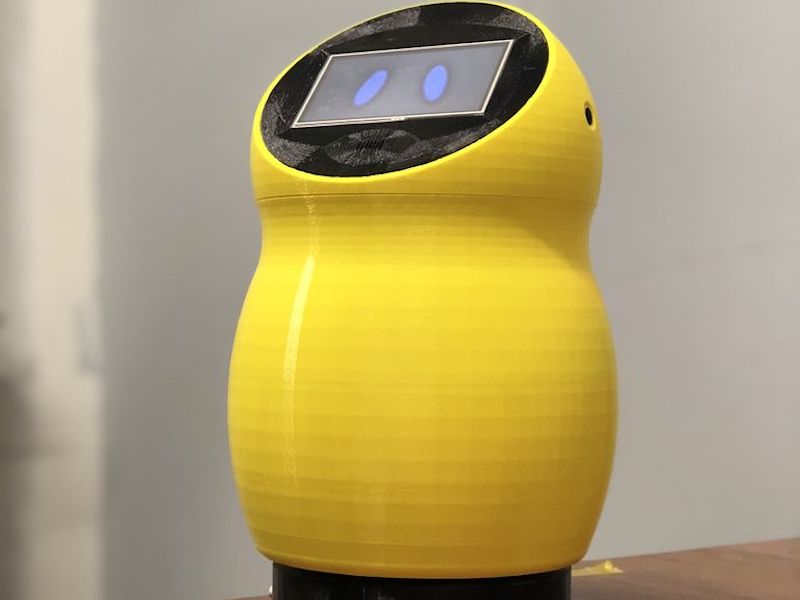
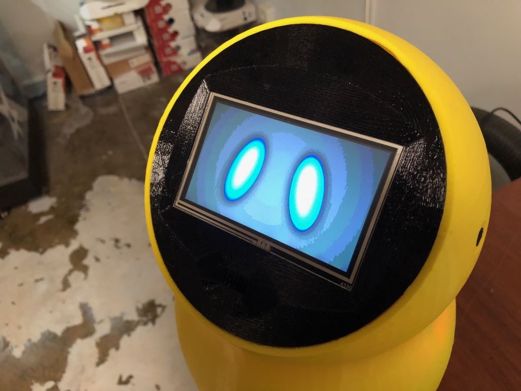
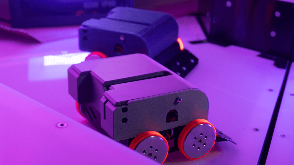
After looking at a lot of different consumer robots, maker projects, and competitive fighting bots, we’ve decided to use the JSUMO BB1 robots for this game. We liked the fact that these bots have a metal casing which makes them very durable, all parts are easily replaceable and can be bought separately, and it has 4 independent motors (motor shields included), one for each wheel, which allows it to rotate on the same spot.
We were pretty skeptical of being able to fit all the electronics into the original casing, but we decided to go with this robot anyways, as it had the best overall characteristics. As this robot is easily modifiable, we can always 3D print an extra casing to fit all the parts.
What is the board?
Now that we’ve decided on the robot, it was the time to define what electronics should we use in this build. As usual, it all starts with the requirements. Here’s what we need for the game to run smoothly:
- The robot should be able to recover from any position
- Can stay online while charging
- Supports WiFi network connection and offers reliable connectivity
- Easily programmable and supports OTA updates
- Can control four motors simultaneously
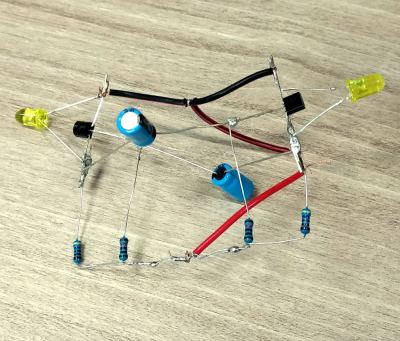
Based on these requirements we had the following electronics layout in mind:

We had to find a board that is energy efficient, can send commands to motors, supports parallel charging and has a small footprint on the robot size. With so many requirements, finding the perfect board can be a challenge.
Arduino to the rescue
Fortunately, Arduino was there to help us out. They offer a rich selection of boards to fit every possible robotics project out there and have very detailed documentation for each of the boards.
More importantly, Arduino is known for its high quality, something that is crucial for semi-autonomous types of applications. Coming from an embedded software background and having to work with all sorts of hardware, we often see that some features or board functionalities are not fully finished which can lead to all sorts of unpleasant situations.
After looking at the Arduino’s collection of boards we quickly found a perfect candidate for our project, the Arduino MKR1000 WiFi. This board fits all of our main requirements for the motor controls, is easily programmable via Arduino IDE, and due to its low power design is extremely power efficient, allowing us to have a lower capacity battery. Additionally, it has a separate WiFi chip onboard, which solely focuses on providing a reliable WiFi connection, something that is very important in our use case.
Now that we’ve decided on the “brain” of our robot, it was time to choose the rest of the components.
Robust hardware means working software
Something to keep in mind is that when working with hardware, you should always try to avoid any possible risks. This means that you should always over-do your minimal hardware requirements where possible. The reason is — if your hardware doesn’t work as intended, your whole software stack becomes unusable too. Always chose reliable hardware components for mission-critical applications.

Some of our electric components might look a bit overkill, but due to the nature of our projects, they are a critical requirement.
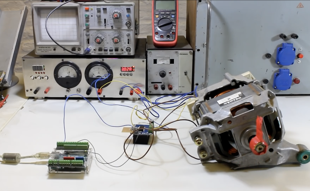
Avoiding the battery explosions
As there is a lot of robot collision involved in the game, we decided to go with a high safety standard battery solution. After evaluating multiple options on the market, we decided to go with the RRC2040 from RRC (Germany). It has a capacity of 2950 mAh that allows us to run the robots for up to five hours on a single charge. It has an internal circuitry for power management, protection features and it supports SMBUS communications (almost like I2C), and is certified for all of the consumer electronics battery standards. For charging, we used RRC’s charging solution designed specifically for this battery and that offers the possibility to feed power to the application while the battery is being charged.
Note: the Arduino MKR1000 has a pretty neat charging solution on the board itself. You can connect the battery to the board directly as the main power source, and you charge it directly through the MKR1000’s micro USB port. We really wanted to use it to save space and have a more robust design, but due to the large capacity of our battery, we couldn’t use it at full potential. In our future projects with smaller scale robots, we definitely plan to use the board’s internal charging system, as it works perfectly for 700-1800 mAh power packs.
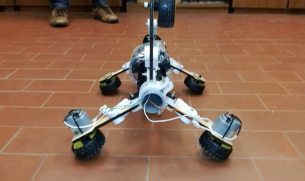
Bot recovery
For the bot to be able to recover from falling on its head, we’ve implemented a flipping servo. We didn’t want to have any risk of not enough torque, so we went with DS3218, which is capable of lifting up to 20KG of weight. Here’s how it works:

Hooking everything together
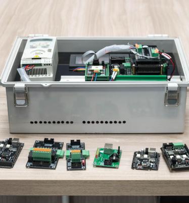
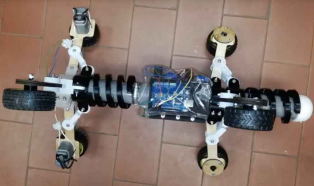
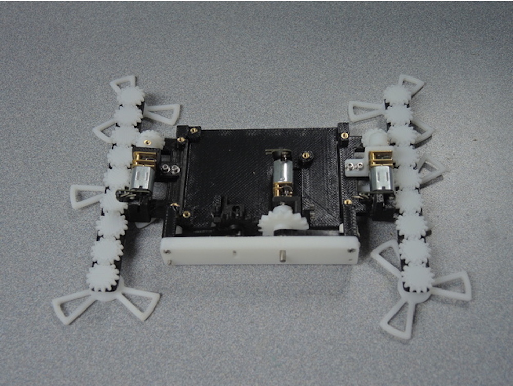
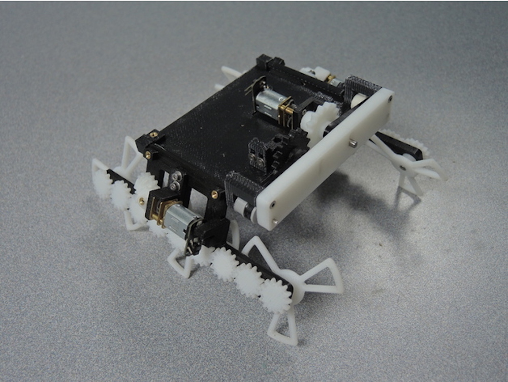
Now that we’ve decided on all of the crucial elements of this setup, it was time to connect all the elements together. As the first step, we figured what would be the best step way to locate all the pieces within the bot. We then 3D-printed a casing to protect the electronics. With all of the preliminary steps completed, we’ve wired all of the components together and mounted them inside of the casing. Here’s how it looks:

It was really convenient for us that all the pins on the board could be connected just by plugging them in, this avoids a lot of time spent on soldering the cables for 12 robots and more importantly, allowed us to cut out the risk of bad soldering that usually can’t be easily identified.
Arduino = Quick code
Arduino MKR1000 offered us the connectivity we needed for the project. Each sumo robot hosts their own UDP server using MKR1000 WiFi libraries to receive their control commands for a central control PC and broadcasting their battery charge status. The user commands are translated to three different PWM signals using Arduino Servo library for the flipping, left and right side motor controllers. The board used has support for hardware PWM output which was useful for us. Overall we managed to keep the whole Arduino code in a few hundred lines of code due to the availability of Servo and Wifi libraries.
The out of the box ArduinoOTA support for updating the code over the WiFi came in handy during the development phase, but also anytime we update the firmware for multiple robots at the same time. No need to open the covers and attach a USB cable! We created a simple Bash script using the OTA update tool bundled in Arduino IDE to send firmware updates to every robot at the same time.
To summarize
It’s pretty amazing that we live in the age where you can use a mass market, small form factor board like the Arduino MKR1000 and have so much functionality. We’ve had a great experience developing our SumoBots Battle Royale game using the board. It made the whole process very smooth and streamlined, the documentation was right on point, and we never had to hit a bottleneck where the hardware wouldn’t work as expected.

More importantly, the boards have proven to be very robust throughout the time. These SumoBots have been used for more than 3,000 games already, and we haven’t seen a single failure from the MKR1000. For a game where you literally slam the robots in to each other at a high speed, that’s pretty impressive to say the least.
We look forward to working with Arduino on our future games, and we can’t wait to see what they will be announcing in 2020!