Posts | Comments

Planet Arduino

Archive for the ‘repair’ Category

No, it’s not the kind of honeycomb you’re probably thinking of. We’re talking about the lightweight panels commonly used in aerospace applications. Apparently they’re rather prone to dents and other damage during handling, so Boeing teamed up with students from the California State University to come up with a way to automate the time-consuming repair process.

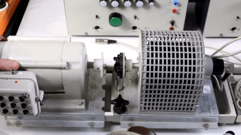
The resulting machine, which you can see in action after the break, is a phenomenal piece of engineering. But more than that, it’s an impressive use of off-the-shelf components. The only thing more fascinating than seeing this robotic machine perform its artful repairs is counting how many of its core components you’ve got laying around the shop.

Built from aluminum extrusion, powered by an Arduino Due, and spinning a Dewalt cut-off tool that looks like it was just picked it up from Home Depot, you could easily source most of the hardware yourself. Assuming you needed to automatically repair aerospace-grade honeycomb panels, anyway.

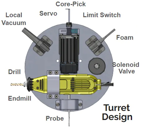
At the heart of this project is a rotating “turret” that holds all the tools required for the repair. After the turret is homed and the condition of all the cutting tools is verified, a hole is drilled into the top of the damaged cell. A small tool is then carefully angled into the hole (a little trick that is mechanical poetry in motion) to deburr the hole, and a vacuum is used to suck out any of the filings created by the previous operations. Finally a nozzle is moved into position and the void is filled with expanding foam.

Boeing says it takes up to four hours for a human to perform this same repair. Frankly, that seems a little crazy to us. But then again if we were the ones tasked with repairing a structural panel for a communications satellite or aircraft worth hundreds of millions of dollars, we’d probably take our time too. The video is obviously sped up so it’s hard to say exactly how long this automated process takes, but it doesn’t seem like it could be much more than a few minutes from start to finish.

Salvaging a beefy motor is one life’s greatest pleasures for a hacker, but, when it comes to using it in a new project, the lack of specs and documentation can be frustrating. [The Post Apocalyptic Inventor] has a seemingly endless stockpile of scavenged motors, and decided to do something about the problem.

Once again applying his talent for junk revival, [TPAI] has spent the last year collecting, reverse-engineering and repairing equipment built in the 1970s, to produce a complete electric motor test setup. Parameters such as stall torque, speed under no load, peak power, and more can all easily be found by use of the restored test equipment. Key operating graphs that would normally only be available in a datasheet can also be produced.

The test setup comprises of a number of magnetic particle brakes, combined power supply and control units, a trio of colossal three-phase dummy loads, and a gorgeously vintage power-factor meter.

Motors are coupled via a piece of rubber to a magnetic particle brake. The rubber contains six magnets spaced around its edge, which, combined with a hall sensor,  are used to calculate the motor’s rotational speed. When power is applied to the coil inside the brake, the now magnetised internal powder causes friction between the rotor and the stator, proportional to the current through the coil. In addition to this, the brake can also measure the torque that’s being applied to the motor shaft, which allows the control units to regulate the brake either by speed or torque. An Arduino slurps data from these control units, allowing characteristics to be easily graphed.

If you’re looking for more dynamometer action, last year we featured this neatly designed unit – made by some Cornell students with an impressive level of documentation.


Nothing says ‘I Love You’ like an old vending machine, and if it is a restored and working vintage Vendo V-80 cola dispenser then you have yourself a winner. [Jan Cumps] from Belgium was assigned the repair of the device in question by a friend. He started off with just a working refrigerator and no electronics. In a series of repairs, he began with replacing the mechanical coin detector’s switches with optical and magnetic sensors to detect the movement of the coin. These sensors are in turn connected to an Arduino which drives the dispensing motor. The motor itself had to be rewound as part of the repair. Since the project is on a deadline, the whole thing is finished using protoboards and through-hole parts. The final system works by dispensing one frosty bottle every time a coin is inserted.

In contrast to most vending machine repairs, this project was a simple one. Instead of using an off-the-shelf coin detector, a simple LED and photodiode pair brought the hack to life. This could easily be adapted to any machine and even be used to create a DIY vending machine on the cheap. 

In his blog, [Jan Cumps] demonstrates each working step in a video and share the Arduino code and schematic as well as other interesting details. You can see the final working version in the video below.

It has been a long time since a Vending Machine Prototyping project was commissioned and we would love to see what this project inspires.


Filed under: Arduino Hacks
May
13

Hello readers

Now and again in the quest to save money, or to buy something that you need when you are short on cash, you inevitably end up trawling through eBay for what you need. Last month I needed some 20V DC 1 amp plugpacks to test my bbboost prototypes with, so naturally after scoping out retail prices eBay found itself on my web browser. Considering a local alternative costs $38, it was worth a shot. As these were for ‘internal use only’, that is for myself and nobody else, it is ok for me to buy the cheaper option. Well it used to be.

These suckers were found for $5.20 delivered from Taiwan…

No C-Tick or electrical authority approvals on this plug pack…

The first problem was the plug – these were advertised as having Australian plugs, however it was the US-style with adaptor. Naturally the adaptor didn’t fit, and I had to disassemble and rearrange the contacts inside for it to accept the flat pins. Second problem was the heat – this little monkey would run hot, even without a load. I asked it for around half an ampere and it really cooked. Ouch!

In the words of Dave Jones – “it’s a piece of sh*t!”

So what else was there to do? Wait for it to cool down, and pull it apart!

Wow – what a mess. Even through the electrolytic capacitors looked normal, there was a layer of brown, rusty goop all over the back of the 2n60C MOSFET. Where did that come from? The mind boggles. Everything else looked normal, the PCB was soldered nicely and the capacitors weren’t bulging or leaking. There were holes for a 1k0 resistor and an LED, but they were unused. What else to do? I cut the DC lead from the housing and soldered a 9v PP3 battery snap on the end – perfect for using an Arduino away from the desk for prototype testing…

So the exercise was a not a total waste… the DC plug is worth $2 locally, and the wire was probably worth about fifty cents. The plastic housing might be useful later on.

From now on I think it will pay to fork out for an approved, locally-sourced adaptor. No more eBay! So remember, quality is remembered long after price is forgotten.

High resolution photos are available on flickr.

As always, thank you for reading and I look forward to your comments and so on. Please subscribe using one of the methods at the top-right of this web page to receive updates on new posts!


  • Newsletter

    Sign up for the PlanetArduino Newsletter, which delivers the most popular articles via e-mail to your inbox every week. Just fill in the information below and submit.

  • Like Us on Facebook