Posts | Comments

Planet Arduino

Archive for the ‘arduino shield’ Category

Core Memory: Why We Used 60-Year-Old Tech in an Arduino Shield

About ten years ago, we designed and made an Arduino shield implementing “core memory,” a technology that was sixty years old even then. Our shield stored 32 individual 1s or 0s using magnetic fields going either clockwise or anticlockwise around 32 tiny doughnuts of magnetisable ‘ferrite’ material. This kind of memory, invented in the 1950s, […]

The post Core Memory: Why We Used 60-Year-Old Tech in an Arduino Shield appeared first on Make: DIY Projects and Ideas for Makers.

There’s no question that you can get a lot done with the classic multimeter; it’s arguably the single most capable tool on your bench. But the farther down the rabbit hole of hacking and reverse engineering you go, the more extravagant your testing and diagnostic gear tends to get. For some of us that’s just an annoying reality of the game. For others it’s an excuse to buy, and maybe even build, some highly specialized equipment. We’ll give you one guess as to which group we fall into here at Hackaday.

[Akshay Baweja] is clearly a member of the second group. He’s recently published a guide on building a very slick intelligent Integrated Circuit tester with a total cost of under $25 USD. Whether you’re trying to identify an unknown chip or verifying your latest parts off the slow-boat from China actually work before installing them in your finished product, this $25 tool could end up saving you a lot of time and aggravation.

[Akshay] walks readers through the components and assembly of his IC tester, which takes the form of a Shield for the Arduino Mega 2560. The custom PCB he designed and had manufactured holds the 20 Pin ZIF Socket as well as the 2.4 inch TFT touch screen. The screen features an integrated micro SD slot which is important as you need the SD card to hold the chip database.

With an IC to test inserted into the ZIF socket, the user can have the tester attempt to automatically ID the chip or can manually enter in a part number to lookup. The source code for the Arduino as well as the chip ID database is up on GitHub for anyone looking to add some more hardware to the device’s testing repertoire.

The importance of good test equipment simply cannot be overstated. Between highly specialized gear like this IC tester to classic instruments such as the oscilloscope, your bench is going to be full of weird and wonderful pieces of equipment before too long.

[Allan Schwartz] decided to document his experience using Fritzing to design, fabricate, and test a custom Arduino shield PCB, and his step-by-step documentation makes the workflow very clear. Anyone who is curious or has been looking for an opportunity to get started will find [Allan]’s process useful to follow. The PCB in question has two shift registers, eight LEDs, eight buttons, and fits onto an Arduino; it’s just complex enough to demonstrate useful design features and methods while remaining accessible.

[Allan] starts with a basic breadboard design, draws a schematic, prototypes the circuit, then designs the PCB and orders it online, followed by assembly and testing. [Allan] had previously taught himself to use Eagle and etched his own PCBs via the toner transfer method, but decided to use Fritzing instead this time around and found it helpful and easy to use.

About a year ago we saw Fritzing put through its paces for PCB design, and at the time found that it didn’t impress much from an engineering perspective. Regardless, as a hobbyist [Allan] found real value in using Fritzing for his project from beginning to end; he documented both the process and his observations in order to help others, and that’s wonderful.


Filed under: Arduino Hacks, how-to

Announced at the 2014 Maker Faire in New York, the latest Arduino WiFi shield is finally available. This shield replaces the old Arduino WiFi shield, while providing a few neat features that will come in very handy for the yet-to-be-developed Internet of Things.

While the WiFi Shield 101 was announced a year ago, the feature set was interesting. The new WiFi shield supports 802.11n, and thanks to a few of Atmel’s crypto chip offerings, this shield is the first official Arduino offering to support SSL.

The new Arduino WiFi Shield 101 features an Atmel ATWINC1500 module for 802.11 b/g/n WiFi connectivity. This module, like a dozen or so other WiFi modules, handles the heavy lifting of the WiFi protocol, including TCP and UDP protocols, leaving the rest of the Arduino free to do the actual work. While the addition of 802.11n  will be increasingly appreciated as these networks become more commonplace, the speed offered by ~n isn’t really applicable; you’re not going to be pushing bits out of an Arduino at 300 Mbps.

Also included on the WiFi shield is an ATECC508A CryptoAuthentication chip. This is perhaps the most interesting improvement over the old Arduino WiFi shield, and allows for greater security for the upcoming Internet of Things. WiFi modules already in the space have their own support for SSL, including TI’s CC3200 series of modules, Particle‘s Internet of Things modules, and some support for the ESP8266.


Filed under: Arduino Hacks

Surely you need yet another way to charge your lithium batteries—perhaps you can sate your desperation with this programmable multi (or single) cell lithium charger shield for the Arduino?! Okay, so you’re not hurting for another method of juicing up your batteries. If you’re a regular around these parts of the interwebs, you’ll recall the lithium charging guide and that rather incredible, near-encyclopedic rundown of both batteries and chargers, which likely kept your charging needs under control.

That said, this shield by Electro-Labs might be the perfect transition for the die-hard-’duino fanatic looking to migrate to tougher projects. The build features an LCD and four-button interface to fiddle with settings, and is based around an LT1510 constant current/constant voltage charger IC. You can find the schematic, bill of materials, code, and PCB design on the Electro-Labs webpage, as well as a brief rundown explaining how the circuit works. Still want to add on the design? Throw in one of these Li-ion holders for quick battery swapping action.

[via Embedded Lab]


Filed under: Arduino Hacks, Microcontrollers
Nov
06

Battery Shield Mounts Underneath The Arduino

arduino, arduino hacks, arduino shield, battery Comments Off on Battery Shield Mounts Underneath The Arduino 

Undershield, DIY Arduino Battery Shield

So, what do you do when your Arduino project needs to operate in a remote area or as a portable device? There are LiPo battery shields available, and although they may work well, recharging requires access to a USB port. You can also go the 9v battery route plugged into the on-board regulator of the Arduino but the low mAh rating of a 9v won’t allow your project to stay running for very long. [AI] needed a quick-change battery option for his Arduino project and came up with what he is calling the AA Undershield.

As the name implies, AA sized batteries are used in the project, two of them actually. Yes, two AA batteries at 1.5v each would equal only 3 volts when connected in series. The Arduino needs 5v so [AI] decided to use a MAX756 DC-to-DC step-up regulator to maintain a steady stream of 5v. This article has some nice graphs showing the difference in performance between a 9v battery being stepped down to 5v verses two AA’s being bumped up to 5v.

The ‘under’ in Undershield comes from this shield being mounted underneath the Arduino, unlike every other shield on the planet. Doing so allows use of a standard 0.100″-spaced prototype PCB and is an easy DIY solution to that odd-sized space between the Arduino’s Digital 7 and 8 pins. The Arduino mounts to the Undershield via its normal mounting holes with the help of some aluminum stand offs.

[AI] did a great job documenting his build with schematics and lots of photos so that anyone that is interested in making one for themselves can do so with extreme ease.


Filed under: Arduino Hacks

Open-source BLDC motor driver

Brushless motors are ubiquitous in RC applications and robotics, but are usually driven with low-cost motor controllers that have to be controlled with RC-style PWM signals and don’t allow for much customization. While there are a couple of open-source brushless drivers already available, [neuromancer2701] created his own brushless motor controller on an Arduino shield.

[neuromancer2701]‘s shield is a sensorless design, which means it uses the back-EMF of the motor for feedback rather than hall effect sensors mounted on the motor. It may seem strange to leave those sensors unused but this allows for less expensive sensorless motors to work with the system. It also uses discrete FETs instead of integrated driver ICs, similar to other designs we have covered. Although he is still working on the back-EMF sensing in his firmware, the shield successfully drives a motor in open-loop mode.

The motor controller is commanded over the Arduino’s serial interface, and will support a serial interface to ROS (Robot Operating System) in the future. This shield could be a good alternative to hobby RC controllers for robots that need a customizable open-source motor controller. The PCB design and source code are available on GitHub.


Filed under: Arduino Hacks
Oct
10

Using Arduino shields with the Raspi

arduino, arduino hacks, arduino shield, Raspberry Pi, Raspi, shield Comments Off on Using Arduino shields with the Raspi 

With hundreds of Arduino shields available for any imaginable application, it’s a shame they can’t be used with the Raspberry Pi. Breaking out the Raspi GPIO pins to Arduino-compatible headers would allow makers and tinkerers to reuse their shields with a far more capable computing platform.

The folks over at Cooking Hacks realized a Raspi to Arduino shield bridge would be an awesome device, so they made their own, complete with a software library that allows you to port your Arduino code directly to the Raspberry Pi.

There are a few limitations with the Raspberry Pi’s GPIO headers; the Raspi doesn’t have analog inputs, so the Cooking Hacks team added an 8-channel ADC. Along with analog inputs and the headers required to pop a shield on the board, there’s also a socket for an XBee module.

The software library contains most of the general Arduino functions such as digitalWrite() and digitalRead(). There Serial, Wire, and SPI libraries are also implemented, allowing any device that communicates through UART, I2C, or SPI to talk directly to the Raspberry Pi.

While the Raspi Arduino bridge doesn’t allow for PWM in the same capacity as an Arduino, you’re always welcome to whip up a servo or LED shield for this neat little adapter.


Filed under: arduino hacks, Raspberry Pi

Hello readers

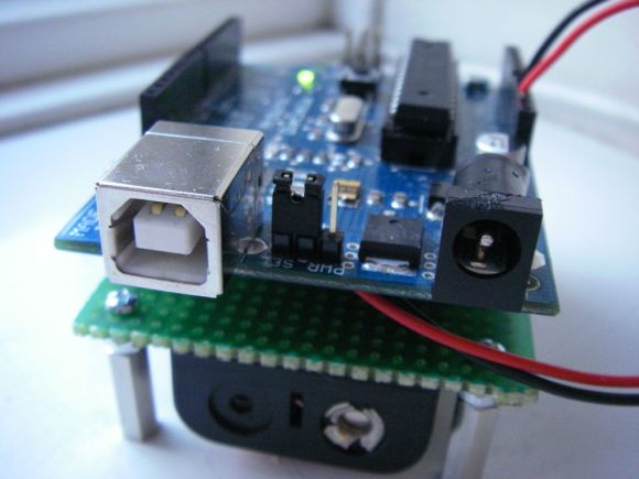
In this article you can follow the process of making another LCD shield for the Arduino Duemilanove or compatible boards. In the past (which explains the word another in this title) I made a 16 x 2 character LCD shield, however it was not backlit, nor large enough. Recently I acquired a 20 x 4 character backlit LCD for use in my Arduino tutorials, therein making this project necessary. To refresh your memories, here is the original shield:

However this time, I cannot mount the display on the shield, it is just too large. Furthermore, it is preferable to be able to stack other shields on top of the new LCD shield. Therefore the display will be external and connected with lengths of wire. So time to get cracking. The first step was to assemble all the parts together. The new LCD has a standard 16-pin  HD44780 interface, and is very easy to connect:

What we have: one 20×4 character backlit LCD, a Freetronics basic protoshield, some stacking pin headers, a button, 10k ohm trimpot for contrast adjustment, and some spacers and matching screws to give the LCD some legs. Afterwards I got some 0.1uF ceramic capacitors as well, to smooth supply current on the 5V rail of the shield. Here is the data sheet for the LCD: 2004 LCD.pdf.

As usual the first thing to do was to make a plan. The LCD interface is easy enough, but I still like to have something on paper to refer to:

The next step is to breadboard it – to make sure it works. However I did solder in the wires to the LCD at this stage:

And after assembling the circuit, a brief test:

Success. The demonstration sketch is the example provided with the Arduino IDE, modified for a 20×04 LCD – 2004LCDdemo.pdf. During the test above, I used an external 5V power supply for the breadboard. Remember to connect the ground line from the Arduino to the ground line of your breadboard, otherwise it will not work. At this point I was wondering how much current the LCD used by itself. The data sheet claimed it was five milliamps… I think not. Mr Multimeter had a different opinion:

Now it was time to finish the soldering work. Instead of trying to jam all the wires together along the digital pins, I used some wire jumpers to spread out the landing points for the wires from the LCD.

Furthermore, I decided to install a power LED and 560 ohm resistor – you can never have too many LEDs. :) The rear of the protoshield was also quite neat, dollops of solder easily bridged pads when required. Then after a visual inspection it was time to solder in the header pins. The easiest way to do this is to use an existing shield:

After soldering in the pins, the first attempt of using the display was unsuccessful. I had confused a couple of wires, but some reprogramming of the sketch fixed that. (It was Saturday night and my eyes were tired). But once the error had been fixed – success!

If this shield/display needed a name, I would call it the Dog’s breakfast. Now, hardware is only half of the solution – there are one or two things to take into account when writing your sketch. If you do not have the latest version of the Arduino IDE (v18), upgrade so you will have the new LiquidCrystal library. Also, when using .setCursor(x,y); to position the cursor, the top left position on the LCD is 0,0; and the bottom right is 19,3. For example, the image below was created by:

lcd.setCursor(0, 0);
lcd.print("A");
lcd.setCursor(1,1);
lcd.print("B");
lcd.setCursor(2,2);
lcd.print("C");
lcd.setCursor(3,3);
lcd.print("D");

Now to make something slightly more useful to take advantage of the screen area – another clock! (I like clocks) using my DS1307 real time clock shield. Here is the sketch: worldclock.pdf, (doesn’t allow for DST) and an action shot:

Question – from which organisation did my LCD module come from? :)

So there you have it. Another way to use an LCD with an Arduino, and show how you can do things yourself.

If you have any questions at all please leave a comment (below). We also have a Google Group dedicated to the projects and related items on the website – please sign up, it’s free and we can all learn something. High resolution photos are available from flickr. This article is a guide – always check your own work before committing to construction.

Otherwise, have fun, stay safe, be good to each other – and make something! :)


  • Newsletter

    Sign up for the PlanetArduino Newsletter, which delivers the most popular articles via e-mail to your inbox every week. Just fill in the information below and submit.

  • Like Us on Facebook