Today we are going to examine a part that makes connecting external wires to an Arduino Duemilanove or 100% compatible board easier than trying to electrocute yourself – the Wingshield Industries ScrewShield. Is is such a simple and useful thing I am almost angry at myself for not getting one earlier. Better late than never!
The ScrewShield allows you to connect wires to all of your Arduino I/O pins via PCB-mounted terminal blocks. And it is also designed as a shield, so you can stack more shields on top like any other. Now to save costs it comes unassembled, but that isn’t a problem. Here is the contents of the bag upon arrival:
The quality of the PCBs are very good:
And no instructions were necessary – so time to fire up the soldering iron and fume extractor (hi Kortuk).
The first thing to do was jig up the socket pins with the PCBs using my favourite method, a lump of blutac:
Then it was a simple matter to turn it over and solder away; then repeat the process for the other wing. Time for a quick break to see how they look:
Once the sockets have been soldered in, the next step was to connect the terminal blocks together for each appropriate line:
And then time for another soldering session:
And we’re done. Looks kind of like a Lego spaceship from my childhood:
You can never have too many Arduino shields:
Another use for the ScrewShield is to make it easy to connect multi-core wires to a breadboard. Using PCB terminal blocks is usually difficult as the pins are a fraction too large for the holes in the average breadboard. However you can only use the analogue shield to do this, as a reader has pointed out, the pin spacing for the digital side is a little off:
Nice one. It’s always great to have a product with more than one use.
So there you have it. Another inexpensive, interesting and very useful part for the Arduino fans out there. If you use an Arduino – you really should get one of these. They are available from the usual retail outlets, and I purchased mine from Little Bird Electronics here in Australia.
If you have any questions at all please leave a comment (below). We also have a Google Group dedicated to the projects and related items on the website – please sign up, it’s free and we can all learn something. High resolution photos are available from flickr.
Otherwise, have fun, stay safe, be good to each other – and make something!
[Note - these parts were purchased by myself personally and reviewed without notifying the manufacturer or retailer]
Today we are going to look at another Arduino protoshield kit, this time one manufactured for Sparkfun. The reason to use such a thing is to enable extra hardware of your choice to be connected easily to your Arduino board. In the past I have detailed other shields, for example an LCD module, a real-time clock, and a microSD shield. However now I have another brand of shield, so let’s take it for a drive and see what happens.
Once again, this shield is a product of the minimalist-packaging school – arriving in just a plastic bag.
These days that is perfectly acceptable, as long as something is safe there’s no need for overpackaging. Not a slip of instructions were to be found, and a quick look at the website only had a link to a third-party tutorial and the shield schematic (pdf). The circuitry is quite simple so nothing more is necessary for construction. So with the schematic on the screen it was time to solder.
First thing is to match the included parts with the schematic:
Considering the price of this kit, I would have expected some pins as well as header sockets – not everyone wants to stack another shield on top. However the PCB is the thickest I have ever seen. The first thing to solder in were the buttons:
Next were the three resistors. There are two 330 ohm to reduce the current to the LEDs and one 10k ohm for the button. The silk-screening has the values on the board, so you can place them effortlessly.
Next are the two 0.1uF ceramic capacitors – they act to smooth the power supply. They are not marked on the board, only little rectangles. So here is a photo of where they should be:
And finally the LEDs. Make sure to line up the flat edge of the LED (the cathode) with the image of the LED on the board. Try and get the LED flush with the PCB, and bend the legs in alternate directions to keep the LED flush while you are soldering it:
The included LEDs are 5mm yellow, so you have the opportunity to change the colour if need be. If you are going to add your own circuitry, you might want to do that before soldering in the header sockets. You could also drop in a micro-breadboard instead. When it comes time to solder in the sockets, I like to insert pins into them, then put the whole lot upside down on a breadboard, and solder them in that way:
Another way is to insert the sockets into your shield, put another shield on top to keep the sockets aligned, then solder them in:
However at the end of the day it works:
There you have it – one Arduino protoshield ready for action. If you look at the top-right of the board, you will notice pinouts that are custom-made for the Bluesmirf wireless serial bluetooth devices.
In general this shield is adequate. There is room for a few improvements, for example nothing on the bottom is labelled, which can be an issue if your eyesight or memory is poor. And considering the price of the board (US$16.95++) it should have included both header pins and sockets, and perhaps even have been assembled except for the headers. But thankfully there are other options to select from. Compared to my personal preference (the Freetronics protoshield), this protoshield from Sparkfun could use some improvement. Perhaps version three ? Only time will tell.
Once again, thank you for reading and I look forward to your comments and so on.
If you have any questions at all please leave a comment (below). We also have a Google Group dedicated to the projects and related items on the website – please sign up, it’s free and we can all learn something.
[Note - this kit was purchased by myself personally and reviewed without notifying the manufacturer or retailer]
Today we are going to look at a micro SD card Arduino shield. The reason to use such a thing is to have a storage dump for any data that you generate with your Arduino project that can accept a very large amount of data – up to several gigabytes if you have a large enough micro SD card. With the appropriate sketch it is also possible to read from the card, navigate file directories and so on, but to keep it simple I am just going to examine the most popular aspect – writing our data to the card. However if enough people ask me I will spend the time to figure out the rest.
Initially I imagined this project would be quite difficult, but after some research it was fine. You’re lucky to not have to do the work completed by myself
Anyhow, moving on. The shield is shipped in the usual minimalist packaging, a plastic bag and the shield:
You will need to supply your own header sockets or pins and fit them yourself. I have found the easiest way to do this is to put the pins in the header sockets, as such:
then push these into a solderless breadboard, with the shield on top upside down:
Then solder away. Before you know it, your shield is complete:
The red board colour is a nice contrast with the blue of my TwentyTen. Now of course you will need a micro SD card to write your data to. Contrary to popular belief you can use SDHC micro SD cards that are larger than two gigabytes in size. First of all, you will need to format your micro SD card. Check the instructions or help system of your computer’s operating system to determine how to do this. However ensure that the format type is either FAT32 or FAT 16, not MacOS or ext3 or NTFS, etc.
Next we need to prepare the Arduino IDE to work with the shield. There is a library of functions that needs to be installed for the project to work. Bill Greman has written an excellent library to use, download it from here. After downloading the library, it needs to be installed into the appropriate directory on your computer’s hard drive. If you are unsure how to do this, please read this tutorial by ladyada. If you use Ubuntu like me, place the extracted folder into /usr/share/arduino/libraries
On the software side of things, please note that the shield requires exclusive use of digital pins 10, 11, 12 and 13 for the SPI interface to the card reader.
The next thing to do is test our new shield. Plug the shield into your Arduino Duemilanove or compatible board, then the micro SD card into the slot. It will need a small amount of pressure, as it “clicks” in. Also note that in order to remove the card, you push it and it pops out a little. Don’t try to just pull it out with your thumbnail. It is also wise to only insert and remove the card when the power is off.
Assuming you have installed your library correctly, fire up the Arduino IDE and select File menu > examples > SDFat > SDFatinfo. Plug in your shield, upload the sketch, then hit the serial monitor button. Enter a character and press enter – you should be presented with something like:
This display shows various data about the card, the formatting type and so on. If it did not work, check your soldering on the shield, re-format the card with FAT16 or FAT32, reseat the shield into the Arduino, reconnect to the PC and try again.
Next it is time to write something to the card, to get a feel for how things work. Run the “SDFatwrite” example, open the serial monitor box, enter a character and press enter. Now open the resulting text file found on your micro SD on your computer. You should have something that looks like:
There really is a lot of code in the demonstration sketch, but to make things easier to adapt, have a look at line 90 to 94 of the sketch.
The writeString() function writes text to the file, just like Serial.write() would to the screen. The writeNumber() function writes integers, or unsigned integers to the file. And the writeCRLF() function starts a new line in the file. You can basically copy and paste the code into your own sketch and use these functions, as long as your variable types are suitable for the functions.
In saying that, I have made a demonstration sketch to prove this. Using the real time clock shield from last week’s articles, an Analog Devices TMP36, and a 560 ohm resistor/LED on digital pin 2, we can make a temperature logger with time and date. This involves a nice stack of Arduino goodness:
and a solderless breadboard with the temperature sensor and the LED setup. If you had a really small breadboard, you could plonk it into the micro SD shield and save space. Alas, mine did not fit.
But it worked. Now for the sketch – you can download it here: demonstationsketch.pdf. If you examine the sketch I have filled it with comments and points of interest. If you are unsure of how the real time clock code works, please visit here. Fore more information about the temperature sensor, please visit here. There was no need to compute Fahnrenheit in the sketch, as this can be done later on in a spreadsheet, saving you sketch memory and storage space.
The purpose of the LED is to let you know when the sketch is about to start, and when it has finished. Once the blinking starts at the end of the sketch, you can power off and remove the micro SD card as the program has written and closed the file. If you do this before the sketch has finished, you may corrupt the file and lose your data.
Here is an example of the file from the demonstration sketch:
Notice how there are distinct columns between the data. This is important as later you may want to import the text file into a spreadsheet to analyse your data. For example, if you use the Insert > Sheet from file… command in the Openoffice.org spreadsheet, you can select which columns of data to import, like this:
Which will leave you with nicely delimited data that you can twist around to your heart’s content:
In this spreadsheet I have calculated the minimum, maximum and average temperature – and in Fahrenheit as well. By just capturing the raw data using the micro SD shield you can offload a lot of processing work from the Arduino and onto your personal computer - a much more efficient solution. The spreadsheet has been places in the files section of our Google Group.
So there you have it. You now have the tool and an understanding of how to capture data from the real world, and bring it home to analyse and make decisions from it. The possibilities are almost limitless, using a wide range of sensors, user inputs, even GPS modules, you can get a better understanding of the world around you.
The shield is available from the usual range of retailers, and this one was purchased from Little Bird Electronics.
As always, thank you for reading and I look forward to your comments and so on. Please subscribe using one of the methods at the top-right of this web page to receive updates on new posts. Or join our new Google Group.
Today we are going to make a real time clock Arduino shield. If you have been following my tutorials, in weeks 7, 8 and onwards we have been making use of the Maxim DS1307 real time clock chip. Although it is a very interesting part to use, implementing it has not been so easy, therefore the reason for this shield. So let’s go!
First of all, we need create our circuit diagram. Thankfully the Maxim DS1307 data sheet [pdf] has this basics laid out on page one. From examining a DS1307 board used in the past, the pull-up resistors used were 10k ohm metal films, so I’m sticking with that value. The crystal to use is 32.768 kHz, and thankfully Maxim have written about that as well in their application notes [pdf], even specifying which model to use. Phew!
So here is the circuit diagram we will follow (click on it to enlarge):
Which gives us the following shopping list:
One arduino protoshield pack. I like the yellow ones from Freetronics, however others may prefer this one
X1 – 32.768 kHz crystal – Citizen America part CFS206. You should probably order a few of these, I broke my first one very quickly…
The first thing to do is create the circuit on a solderless breadboard. It is much easier to troubleshoot possible issues before soldering the circuit together. Here is the messy test:
Messy or not, it worked. Instead of writing another sketch, the example 7.3 from arduino tutorial seven was used. Here is a copy: example 7.3.pdf.
The next step is to consider the component placement and wiring for the protoshield. Try not to rush this step, and triple-check your layout against the schematic. As my protoshield has a green and red LED as well, I have wired the square-wave output to the green LED. You can never have too many blinking lights…
At this point I celebrated the union of tea and a biscuit. After returning to the desk, I checked the layout once more, and planned the solder bridges. All set – it was time to solder up. If you have the battery in the holder for some reason, you should remove it now, as they do not like getting warm. Furthermore, that crystal is very fragile, so please solder it in quickly.
And here we are – all soldering done except for the header sockets. At this point I used the continuity function of the multimeter to check the solder joints and make sure nothing was wrong with the circuit.
Final checks passed, so on with the headers. To make this easier, I stick some header pins in the sockets, then place the whole lot in a solderless breadboard to keep it straight. Well, it works for me:
Just a side note – always make sure you have enough consumables, the right tools, etc., before you start a project. This is how much solder I had left afterwards…
Moving on … in with the battery and the DS1307 – we’re done!
It is now time for the moment of truth – to insert the USB cable and re-run the sketch… and it worked! The blinking LED was too bright for me, so I de-soldered the wire. If you are making a shield, congratulations to you if yours worked as well. If it did not, don’t be afraid to hit me up via email or our Google Group with your questions. Note that if you are using this shield, you cannot use analog pins 4 and 5 – they are being used as the I2C bus. Time to clear up the desk and wash my hands.
Now to put this shield to work. Last week we made an LCD module shield – so let’s pile up the shields and make a digital clock. We can re-use the sketch from arduino tutorial example 7.4, with the liquidcrystal() corrected to use the LCD shield pins. Here is the modified sketch: ds1307shielddemo.pdf.
And my post wouldn’t be complete without a video, so here are our new shields in action!
So there we have it. Another useful shield, and proof that the Arduino system makes learning easy and fun. High resolution photos are available on flickr. If you have any questions or comments, please leave them below, or consider joining our Google Group!
As always, thank you for reading and I look forward to your comments and so on. Please subscribe using one of the methods at the top-right of this web page to receive updates on new posts!
Hello once again to our regular Arduino tutorial instalment. This week are up to all sorts of things, including: distance sensing, using prototyping shields, even more shiftiness with shift registers and 4-digit 7-segment displays, and some exercises to refresh and expand your knowledge. Wow – let’s get cracking…
Do you know how to keep your distance? Some people do, some do not. The same goes for mechatronical things (i.e. robots, those little autonomous vacuum cleaners, etc). So to solve that problem you can integrate a distance sensor into your design. Hopefully by following this section you will gain an understanding of such sensors, and be able to make use of them later on in your own projects. Anyhow, today we are looking at the Sharp GP2Y0A21YK0F infra-red distance sensor. What a mouthful… The funny thing is that it looks like a robot head:
That white JST connector is for three leads, +5V, GND, and analogue out. When purchasing it you should also get a matching lead to save time and mucking about.
How it works is quite simple (I must stop writing that, some things are not as simple as they seem…) – the sensor contains an infra-red transmitter and a receiver. It returns a voltage that is relative to the distance between itself and the object in front of it. This output voltage is inversely proportional to the distance; which is explained better with this graph from the data sheet:
However it is always fun to test these things out yourself. So I placed a sensor up over my desk, measured out 80cm, and attached the multimeter to the analogue output of the sensor.
A crude setup but effective. I held a white piece of cardboard in front of the sensor, starting from more than one metre away, then moved closer to the minimum, then back out again. As shown in this video clip:
Although watching that multimeter may not have been too interesting, hopefully the next task will be!
Exercise 6.1
Using the values from the graph from the Sharp data sheet (above), make yourself a distance-measuring device. Use an LCD module to display the measurements. Metric and imperial! This shouldn’t be too hard at all, you’re just using one analogue input from the sensor, some basic maths, and displaying some data on an LCD. Furthermore, to make it truly portable, you could wire up a 9v PP3 battery to a DC plug and use it for power. A hint – before calculating distances, run a sketch to just return the analogRead() value from the sensor. Then you can make your own judgement on voltage-distance calculations. To save time I used the Electronic Bricks to rapidly construct this prototype.
You will need:
Your standard Arduino setup (computer, cable, Duemilanove)
Finally, my sketch for the solution: Exercise 6.1.pdf. You may have to adjust the values in the decision tree for more accuracy. After spending some time with this sensor, I wouldn’t rely on it for exact distance calculations, however it would be very useful for general item detection, air switches and so on. In the next week or two we will examine another type of distance sensor.
What else could this be used for? Robotics sensors, burglar alarms, switching things on and off. Hopefully you have gained some knowledge about this sensor and have some ideas for implementation.
Coffee time.
Now that we have spent a few weeks constructing our prototypes on breadboards and electronic bricks, it is now time to look at how we can do this in a more compact, and/or permanent method. As you already know, the Arduino system allows for “shields”, PCBs that plug on top of your Arduino board to add some sort of extra functionality. One of these was the Electronic Brick chassis, another popular shield is the ethernet shield.
Well that’s all very nice, but can we do this ourselves? Of course. You need a prototyping shield. There are two main types of protoshield, one that contains a small solderless breadboard that can be used on the shield:
or a shield that is plainly a PCB, ready to solder a circuit onto it. This one below is great, it includes two extra LEDs and a button. Furthermore, the yellow PCB makes things easier to see:
As you can imagine, one is more permanent than the other. In this chapter you can follow me create my own circuit on the plain PCB protoshield.
Recently I purchased a couple of blank protoshields (the yellow one above) in order to make a shield with two 7-segment LED displays and 74HC595 shift registers – as it takes a long time to wire these up on a breadboard. So after composing a diagram of which pins are connected to which pins, it was time to place the components and start soldering.
The board basically a matrix of through-plated holes, so you can solder into them from both sides. Which makes linking them together very simple:
However you really need to be careful planning your board, top and bottom, to avoid things getting messy:
Another trap to look out for is trying to squeeze too much in at once. This can cause you to do some very creative soldering:
The plan was to have two wires in the one hole, a lead and a resistor tail. Very difficult for me to do neatly. However at the end it all came together… somehow!
With this example, some wires have been soldered on the read. In fact, most of them were on the rear. Anyhow, the last thing to do is solder in the header pins in order for our new protoshield to stack on top of our Arduino. You can either solder on full header sockets, just like the Arduino, or pins if you don’t need to stack another shield on top of yours. In this case you would not cover up the displays, so only pins will be used. The best way to solder the pins is to place them into your Arduino, put your shield on top, then solder. Example:
And once it came time to set my shield down on the pins, a very amusing (to me) thing happened – it would not sit straight! All those wires underneath the PCB interfered with the microcontroller on the Arduino itself:
So there is a useful tip for you: always plan your protoshields in all three dimensions! Otherwise things may not go as planned, and you don’t want a leaning tower of shields. But finally, it did work with some careful wire repositioning:
So there you have it, a quick demonstration of what to do and not do when using a blank prototyping shield. In the near future we shall make more use of these.
Moving on…
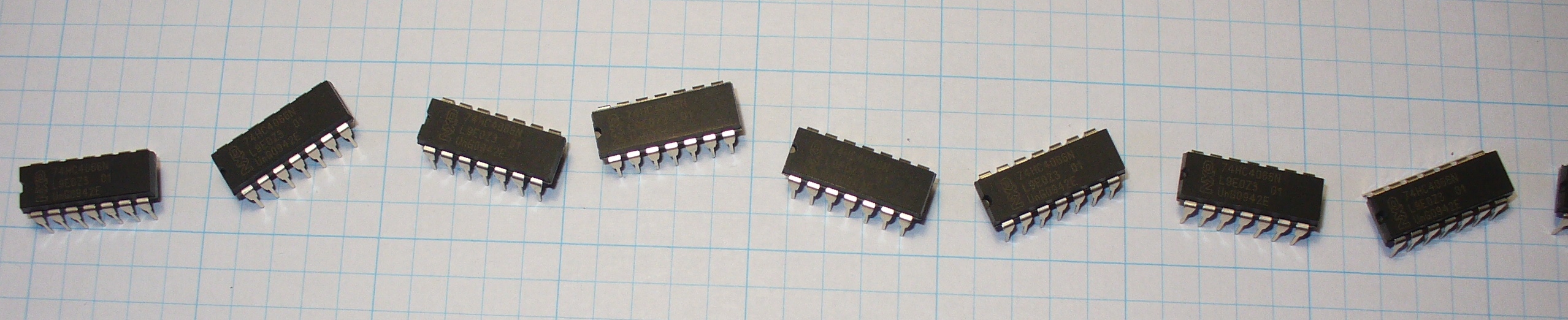
In previous instalments we have worked with 7-segment LED displays, using up to three at once, being controlled by 74HC595 shift registers. As you may have realised by now that involved a lot of wiring, resistors, time and effort. But what if you need four or more digits? Use an LCD… Maybe. Sometimes you need to use LED displays for aesthetic reasons, price, clarity, or just because you love that LED look. Thankfully you can find four digit displays, instead of having to use 2 x 2 or 4 x 1 digit displays. Let’s have a look at one now:
For the newcomer there would be a surprising lack of pins on this display module. That is a good thing, and a slightly tricky thing – but we can overcome the obstacles and use it very easily. How? Again, with two 74HC595 shift registers and some brainpower. Firstly, let’s have a look at the pins – from left to right they are: E, D, C, G, F, B, A, C1, C2, C3, C4, decimal point, unused, unused. This display is common cathode, so to display (for example) the number 1 on digit 3, you would apply ~+2 volts to pins 6 and 7, and attach ground to pin 10. Very much the same as using a single-digit display, except you need to choose the cathode that corresponds with the digit you wish to use. In this tutorial we are using a Common Cathode unit. Out of curiosity’s sake, here is the data sheet for the module used in this chapter: data sheet.pdf.
Secondly, how are we going to control the cathodes with out Arduino? Current comes out of a cathode, so it would not accept a signal from our digital out pins. What we need to do is have a simple switch on each cathode between the display pin and ground, so we can control which digit we want to use. How can we do this with our Arduino? Easy… we can use a simple NPN transistor as a switch. Remember we did this with a relay in chapter three!
But using 4 digital out pins for cathode control is a waste of pins, we can use our trusty shift register again to control the cathodes. So that means we need two shift registers in total, the first to control the digit (0~9), and the second to switch on the cathode of the position we wish to display our digit in. Time to do it!
The first (left-hand) shift register from the Arduino controls the segments on the display, via 560 ohm resistors. Just like last time. The second (right-hand) shift register controls the cathodes. Pins Q0~Q3 connect to the base of a BC548 transistor via a 1k ohm resistor. The collector of the transistor is connected to the cathode on the display, and the emitter to ground. For example:
Note that the schematic above is a guide only. But here it is in real life, below:
After a few projects, wiring up displays and shift registers should be a lot quicker for you now. Here is the matching sketch I came up with for the demonstration video below: Example 6.1.pdf
You’d have to admit, even in the year 2010, LED displays still look mesmerising. Or maybe that’s just me! Here is the data sheet display.pdf for the LED display I used. You can use other ones,as long as they are common cathode; just match the LED element pins with your first shift register, and the cathode pins with the second shift register.
But on to making something useful…
Exercise 6.2
Using the hardware from example 6.1 above, create a device that displays the value of an analogue sensor. For example, if we connect a 10k variable resistor to an analogue input, the Arduino will return a reading of between 0 and 1023. From a hardware perspective, all you need to do is add an analogue sensor (e.g. LDR, 10k variable resistor, the infra-red sensor from earlier on, etc.). The software will be a little tricky, but if you completed exercise 5.1, or 5.2 you shouldn’t have a problem at all. As you will be displaying one digit at a time, but very quickly, try to minimise the number of times you clear the display – in doing so you will keep the brightness at a maximum.
You will need:
Your standard Arduino setup (computer, cable, Duemilanove)
One 4-digit, 7-segment LED display, common cathode
That wasn’t too hard was it? Now that you can use such a display, it will become easier to display output from your various projects.
Another week over! And again, I’m already excited about writing the next instalment… Congratulations to all those who took part and built something useful! Please subscribe (see the top right of this page) to receive notifications of new articles. High resolution photos are available from flickr.
If you have any questions at all please leave a comment (below). If you would like to showcase your work from this article, email a picture or a link to john at tronixstuff dot com.
You might even win a prize. Don’t forget to check out the range of gear at Little Bird Electronics!
Planet Arduino is, or at the moment is wishing to become, an aggregation of public weblogs from around the world written by people who develop, play, think on Arduino platform and his son. The opinions expressed in those weblogs and hence this aggregation are those of the original authors. Entries on this page are owned by their authors. We do not edit, endorse or vouch for the contents of individual posts. For more information about Arduino please visit www.arduino.cc
You are currently browsing the archives for the arduino shield category.