Sure, [Ty Palowski] could have just hung a tennis ball from the ceiling, but that would mean getting on a ladder, testing the studfinder on himself before locating a ceiling joist, and so on. Bo-ring. Now that he finally has a garage, he’s not going to fill it with junk, no! He’s going to park a big ol’ Jeep in it. Backwards.
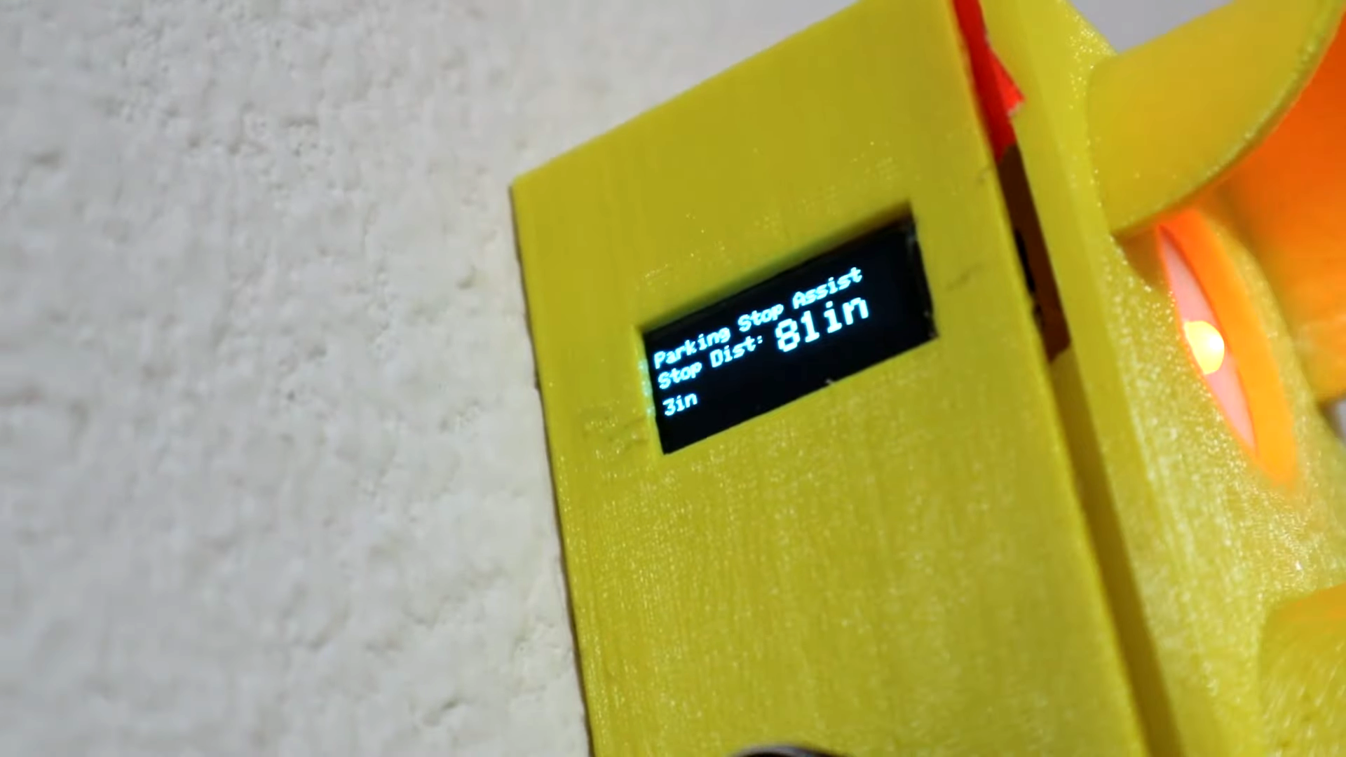
Inside the light is an Arduino Nano, which reads from the ultrasonic sensor mounted underneath the enclosure and lights up the appropriate LED depending on the car’s distance. All [Ty] has to do is set the distance that makes the red light come on, which he can do with the rotary encoder on the side and confirm on the OLED. The distance for yellow and green are automatically set from red — the yellow range begins 24″ past red, and green is another 48″ past yellow. Floor it past the break to watch the build video.
Some of us are oblivious to how often we touch our faces. The current finding is we reach for our eyes, nose, or mouth every three to four minutes. Twenty times per hour is an awful lot of poking, picking, itching, and prodding when we’re supposed to keep our hands away from glands that can transmit and receive disease. To curb this habit and enter the 2020 Hackaday Prize, [Lloyd lobo] built a proof-of-concept device that sounds the alarm when you reach for your face.
We see an Arduino Uno connected to the classic HC-SR04 ultrasonic distance sensor, an LED, and we have to assume a USB battery pack. [Lloyd] recommends the smaller Nano, we might reach for the postage-stamp models and swap the ultrasonic module out for the much smaller laser time of flight sensor. At its soul, this is an intruder alarm. Instead of keeping siblings out of your room, you will be keeping your hands out of the area below the bill of the hat where the sensor is mounted. If you regularly lift a coffee cup to your lips, it might chastise you, and if you chew sunflower seeds, you might establish a tempo. *crunch* *chip* *beep* *crunch* *chip* *beep*
Hello once again to our regular Arduino tutorial instalment. This week are up to all sorts of things, including: distance sensing, using prototyping shields, even more shiftiness with shift registers and 4-digit 7-segment displays, and some exercises to refresh and expand your knowledge. Wow – let’s get cracking…
Do you know how to keep your distance? Some people do, some do not. The same goes for mechatronical things (i.e. robots, those little autonomous vacuum cleaners, etc). So to solve that problem you can integrate a distance sensor into your design. Hopefully by following this section you will gain an understanding of such sensors, and be able to make use of them later on in your own projects. Anyhow, today we are looking at the Sharp GP2Y0A21YK0F infra-red distance sensor. What a mouthful… The funny thing is that it looks like a robot head:
That white JST connector is for three leads, +5V, GND, and analogue out. When purchasing it you should also get a matching lead to save time and mucking about.
How it works is quite simple (I must stop writing that, some things are not as simple as they seem…) – the sensor contains an infra-red transmitter and a receiver. It returns a voltage that is relative to the distance between itself and the object in front of it. This output voltage is inversely proportional to the distance; which is explained better with this graph from the data sheet:
However it is always fun to test these things out yourself. So I placed a sensor up over my desk, measured out 80cm, and attached the multimeter to the analogue output of the sensor.
A crude setup but effective. I held a white piece of cardboard in front of the sensor, starting from more than one metre away, then moved closer to the minimum, then back out again. As shown in this video clip:
Although watching that multimeter may not have been too interesting, hopefully the next task will be!
Exercise 6.1
Using the values from the graph from the Sharp data sheet (above), make yourself a distance-measuring device. Use an LCD module to display the measurements. Metric and imperial! This shouldn’t be too hard at all, you’re just using one analogue input from the sensor, some basic maths, and displaying some data on an LCD. Furthermore, to make it truly portable, you could wire up a 9v PP3 battery to a DC plug and use it for power. A hint – before calculating distances, run a sketch to just return the analogRead() value from the sensor. Then you can make your own judgement on voltage-distance calculations. To save time I used the Electronic Bricks to rapidly construct this prototype.
You will need:
Your standard Arduino setup (computer, cable, Duemilanove)
Finally, my sketch for the solution: Exercise 6.1.pdf. You may have to adjust the values in the decision tree for more accuracy. After spending some time with this sensor, I wouldn’t rely on it for exact distance calculations, however it would be very useful for general item detection, air switches and so on. In the next week or two we will examine another type of distance sensor.
What else could this be used for? Robotics sensors, burglar alarms, switching things on and off. Hopefully you have gained some knowledge about this sensor and have some ideas for implementation.
Coffee time.
Now that we have spent a few weeks constructing our prototypes on breadboards and electronic bricks, it is now time to look at how we can do this in a more compact, and/or permanent method. As you already know, the Arduino system allows for “shields”, PCBs that plug on top of your Arduino board to add some sort of extra functionality. One of these was the Electronic Brick chassis, another popular shield is the ethernet shield.
Well that’s all very nice, but can we do this ourselves? Of course. You need a prototyping shield. There are two main types of protoshield, one that contains a small solderless breadboard that can be used on the shield:
or a shield that is plainly a PCB, ready to solder a circuit onto it. This one below is great, it includes two extra LEDs and a button. Furthermore, the yellow PCB makes things easier to see:
As you can imagine, one is more permanent than the other. In this chapter you can follow me create my own circuit on the plain PCB protoshield.
Recently I purchased a couple of blank protoshields (the yellow one above) in order to make a shield with two 7-segment LED displays and 74HC595 shift registers – as it takes a long time to wire these up on a breadboard. So after composing a diagram of which pins are connected to which pins, it was time to place the components and start soldering.
The board basically a matrix of through-plated holes, so you can solder into them from both sides. Which makes linking them together very simple:
However you really need to be careful planning your board, top and bottom, to avoid things getting messy:
Another trap to look out for is trying to squeeze too much in at once. This can cause you to do some very creative soldering:
The plan was to have two wires in the one hole, a lead and a resistor tail. Very difficult for me to do neatly. However at the end it all came together… somehow!
With this example, some wires have been soldered on the read. In fact, most of them were on the rear. Anyhow, the last thing to do is solder in the header pins in order for our new protoshield to stack on top of our Arduino. You can either solder on full header sockets, just like the Arduino, or pins if you don’t need to stack another shield on top of yours. In this case you would not cover up the displays, so only pins will be used. The best way to solder the pins is to place them into your Arduino, put your shield on top, then solder. Example:
And once it came time to set my shield down on the pins, a very amusing (to me) thing happened – it would not sit straight! All those wires underneath the PCB interfered with the microcontroller on the Arduino itself:
So there is a useful tip for you: always plan your protoshields in all three dimensions! Otherwise things may not go as planned, and you don’t want a leaning tower of shields. But finally, it did work with some careful wire repositioning:
So there you have it, a quick demonstration of what to do and not do when using a blank prototyping shield. In the near future we shall make more use of these.
Moving on…
In previous instalments we have worked with 7-segment LED displays, using up to three at once, being controlled by 74HC595 shift registers. As you may have realised by now that involved a lot of wiring, resistors, time and effort. But what if you need four or more digits? Use an LCD… Maybe. Sometimes you need to use LED displays for aesthetic reasons, price, clarity, or just because you love that LED look. Thankfully you can find four digit displays, instead of having to use 2 x 2 or 4 x 1 digit displays. Let’s have a look at one now:
For the newcomer there would be a surprising lack of pins on this display module. That is a good thing, and a slightly tricky thing – but we can overcome the obstacles and use it very easily. How? Again, with two 74HC595 shift registers and some brainpower. Firstly, let’s have a look at the pins – from left to right they are: E, D, C, G, F, B, A, C1, C2, C3, C4, decimal point, unused, unused. This display is common cathode, so to display (for example) the number 1 on digit 3, you would apply ~+2 volts to pins 6 and 7, and attach ground to pin 10. Very much the same as using a single-digit display, except you need to choose the cathode that corresponds with the digit you wish to use. In this tutorial we are using a Common Cathode unit. Out of curiosity’s sake, here is the data sheet for the module used in this chapter: data sheet.pdf.
Secondly, how are we going to control the cathodes with out Arduino? Current comes out of a cathode, so it would not accept a signal from our digital out pins. What we need to do is have a simple switch on each cathode between the display pin and ground, so we can control which digit we want to use. How can we do this with our Arduino? Easy… we can use a simple NPN transistor as a switch. Remember we did this with a relay in chapter three!
But using 4 digital out pins for cathode control is a waste of pins, we can use our trusty shift register again to control the cathodes. So that means we need two shift registers in total, the first to control the digit (0~9), and the second to switch on the cathode of the position we wish to display our digit in. Time to do it!
The first (left-hand) shift register from the Arduino controls the segments on the display, via 560 ohm resistors. Just like last time. The second (right-hand) shift register controls the cathodes. Pins Q0~Q3 connect to the base of a BC548 transistor via a 1k ohm resistor. The collector of the transistor is connected to the cathode on the display, and the emitter to ground. For example:
Note that the schematic above is a guide only. But here it is in real life, below:
After a few projects, wiring up displays and shift registers should be a lot quicker for you now. Here is the matching sketch I came up with for the demonstration video below: Example 6.1.pdf
You’d have to admit, even in the year 2010, LED displays still look mesmerising. Or maybe that’s just me! Here is the data sheet display.pdf for the LED display I used. You can use other ones,as long as they are common cathode; just match the LED element pins with your first shift register, and the cathode pins with the second shift register.
But on to making something useful…
Exercise 6.2
Using the hardware from example 6.1 above, create a device that displays the value of an analogue sensor. For example, if we connect a 10k variable resistor to an analogue input, the Arduino will return a reading of between 0 and 1023. From a hardware perspective, all you need to do is add an analogue sensor (e.g. LDR, 10k variable resistor, the infra-red sensor from earlier on, etc.). The software will be a little tricky, but if you completed exercise 5.1, or 5.2 you shouldn’t have a problem at all. As you will be displaying one digit at a time, but very quickly, try to minimise the number of times you clear the display – in doing so you will keep the brightness at a maximum.
You will need:
Your standard Arduino setup (computer, cable, Duemilanove)
One 4-digit, 7-segment LED display, common cathode
That wasn’t too hard was it? Now that you can use such a display, it will become easier to display output from your various projects.
Another week over! And again, I’m already excited about writing the next instalment… Congratulations to all those who took part and built something useful! Please subscribe (see the top right of this page) to receive notifications of new articles. High resolution photos are available from flickr.
If you have any questions at all please leave a comment (below). If you would like to showcase your work from this article, email a picture or a link to john at tronixstuff dot com.
You might even win a prize. Don’t forget to check out the range of gear at Little Bird Electronics!
Planet Arduino is, or at the moment is wishing to become, an aggregation of public weblogs from around the world written by people who develop, play, think on Arduino platform and his son. The opinions expressed in those weblogs and hence this aggregation are those of the original authors. Entries on this page are owned by their authors. We do not edit, endorse or vouch for the contents of individual posts. For more information about Arduino please visit www.arduino.cc
You are currently browsing the archives for the distance sensor category.

 The previous owner was kind enough to leave a workbench in the rear of the garage, which [Ty] has already made his own. To make sure that he never hits the workbench while backing into the garage, [Ty] made an adorable stoplight to help gauge the distance to it. Green mean’s he’s good, yellow means he should be braking, and red of course means stop in the name of power tools.