Posts | Comments

Planet Arduino

Archive for the ‘amplifier’ Category

DIy Arduino FM radio enclosure with the lid off, showing the electronics inside

Older hackers will remember that a crystal set radio receiver was often one of the first projects attempted.  Times have changed, but there’s still something magical about gathering invisible signals from the air and listening to the radio on a homemade receiver. [mircemk] has brought the idea right up to date by building an FM radio with an OLED display, controlled with a rotary encoder.

The design is fairly straightforward, based as it is on another project that [mircemk] found on a Chinese site, but the build looks very slick and would take pride of place on any hacker’s workbench. An Arduino Due forms the heart of the project, controlling a TEA5767 module, an SH1106 128×64 pixel OLED display and a rotary encoder. The sound signal is passed through an LM4811 headphone amplifier for private listening, and a PAM8403 Class D audio amplifier for the built-in loudspeaker. The enclosure is made from PVC panels, and accented with colored adhesive tape for style.

It’s easier than ever before to quickly put together projects like this by connecting pre-built modules and downloading code from the Internet, but that doesn’t mean it’s not a worthwhile way to improve your skills and make some useful devices like this one. There are so many resources available to us these days and standing on the shoulders of giants has always been a great way to see farther.

We’ve shown some other radio projects using Arduinos and the TEA5767 IC in the past, such as this one on a tidy custom PCB, and this one built into an old radio case.

We live in a world in which nearly any kind of gadget or tool you can imagine is just a few clicks away. In many respects, this has helped fuel the maker culture over the last decade or so; now that people aren’t limited to the hardware that’s available locally, they’re able to create bigger and better things than ever before. But it can also have a detrimental effect. One has to question, for instance, why they should go through the trouble of building something themselves when they could buy it, often for less than the cost of the individual components.

The critic could argue that many of the projects that grace the pages of Hackaday could be supplanted with commercially available counterparts. We don’t deny it. But the difference between buying a turn-key product and building an alternative yourself is that you can make it exactly how you want it. That is precisely why [Sam Izdat] created this truly one of a kind microphone preamplifier. Could he have bought one online for cheaper? Probably. Could he have saved himself an immense amount of time and effort? Undoubtedly. Do we care? Not in the slightest.

The amplifier is based on the Texas Instruments INA217 chip, with an Arduino Nano and 128×64 OLED display providing the visualization. [Sam] was able to find a bare PCB for a typical INA217 implementation on eBay for a few bucks (see what we mean?), which helped get him started and allowed him to spend more time on the software side of things. His visualization code offers a number of interesting display modes, uses Fast Hartley Transforms, and very nearly maxes out the Arduino.

But perhaps no element of this build is as unique as the case. The rationale behind the design is that [Sam] wanted to compartmentalize each section of the device (power supply, amplifier, visualization) to avoid any interference. The cylindrical shapes were an issue of practicality: the compartments were constructed by using a hole saw to make wooden discs, which were then glued together and hollowed out. The case was stained and coated with polyurethane, but due to some slightly overzealous use of glue and fillers, the coloring isn’t uniform. This gives the final piece a somewhat weathered look, in sharp contrast to the decidedly high-tech looking display.

Overall, this build reminds us of the modular 3D printed amplifier we saw earlier in the year combined with these speaker-integrated Arduino VU meters.

From context clues, we can tell that [TVMiller] has been in and around NYC for some time now. He has observed a crucial weakness in the common metropolitan. Namely, they deafen themselves with earphones, leaving them senseless in a hostile environment.

To fix this problem, he came up with a simple hack, the metrophone. An ultrasonic sensor is hung from a backpack. The user’s noise making device of choice is plugged into one end, and the transducer into the other. When the metropolitan is approached from the rear by a stalking tiger or taxi cab, the metrophone will reduce the volume and allow the user to hear and respond to their impending doom. Augmentation successful.

The device itself consists of an off-the-shelf ultrasonic sensor, an Arduino, and a digital potentiometer. It all fits in a custom 3D printed enclosure and runs of two rechargeable coin cells. A simple bit of code scales the volume to the current distance being measured by the ultrasonic sensor once a threshold has been met.

In the video after the break, you can observe [TVMiller]’s recommended method for tranquilizing and equipping a metropolitan in its natural habitat without disturbing its patterns or stressing it unduly.

The HackadayPrize2016 is Sponsored by:

Filed under: Arduino Hacks, robots hacks
Nov
22

Old Kit Review – Silicon Chip Mini Stereo Amplifier

amplifier, dick, DSE, Electronics, k5008, kit, kit review, review, smith, stereo, stmicro, TDA2822, tronixstuff Comments Off on Old Kit Review – Silicon Chip Mini Stereo Amplifier 

Introduction

In this review of an older kit we examine the aptly-named “Mini Stereo Amplifier” from Dick Smith Electronics (catalogue number K5008), based on the article published in the October 1992 issue of Silicon Chip magazine.

The purpose of the kit is to offer a stereo 1W+1W amplifier for use with portable audio devices that only used headphones, such as the typical portable tape players or newly available portable CD players. I feel old just writing that. At the time it would have been quite a useful kit, paired with some inexpensive speakers the end user would have a neat and portable sound solution. So let’s get started.

Assembly

Larger kits like this one that couldn’t be retailed on hanger cards shipped in corrugated cardboard boxes that were glued shut. They looked good but as soon as a sneaky customer tore one open “to have a look” it was ruined and hard to sell:

Dick Smith Electronics K5008 Stereo Amplifier Kit box

The amplifier kit was from the time when DSE still cared about kits, so you received the sixteen page “Guide to Kit Construction” plus the kit instructions, nasty red disclaimer sheet, feedback card, plus all the required components and the obligatory coil of solder that was usually rubbish:

Dick Smith Electronics K5008 Stereo Amplifier Kit all contents

However the completeness of the kit is outstanding, everything is included for completion including an enclosure and handy front panel sticker:

Dick Smith Electronics K5008 Stereo Amplifier Kit enclosure face sticker

… all the sockets, plenty of jumper wire and even the rubber feet:

Dick Smith Electronics K5008 Stereo Amplifier Kit components

The PCB is from the old-school of design – without any silk-screening or solder mask:

Dick Smith Electronics K5008 Stereo Amplifier Kit PCB front

Dick Smith Electronics K5008 Stereo Amplifier Kit PCB rear

However the instructions are quite clear so you can figure out the component placement easily. Which brings us to that point – all the components went in with ease:

Dick Smith Electronics K5008 Stereo Amplifier Kit PCB partial assembly

… then it was a matter of wiring in the sockets, volume potentiometer and power switch:

Dick Smith Electronics K5008 Stereo Amplifier Kit socket wiring

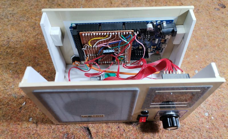
Instead of using a 3.5mm phono socket for power input, I used a 9V battery snap instead. The amplifier can run on voltages down to 1.8V so it will do for the limited use I have in mind for the amplifier. However in the excitement of assembly I forgot the power switch:

Dick Smith Electronics K5008 Stereo Amplifier Kit PCB forgot the switch

However it wasn’t any effort to rectify that. You will also notice three links on the PCB, which I fitted instead of making coils (more on this later). So at that point the soldering work is finished:

Dick Smith Electronics K5008 Stereo Amplifier Kit PCB finished

Now to drill out the holes on the faceplate. Instead of tapering out the slots on the side of the housing, I just drilled all the holes on the front panel:

Dick Smith Electronics K5008 Stereo Amplifier Kit panel

Turns out the adhesive on the front panel sticker had lost its mojo, so I might head off and get some white-on-black tape for the label maker. However in the meanwhile we have one finished mini stereo amplifier, which reminds me of an old grade seven electronics project:

Dick Smith Electronics K5008 Stereo Amplifier Kit finished

How it works

The amplifier is based on the STMicro TDA2822M (data sheet .pdf) dual low-voltage amplifier IC. In fact the circuit is a slight modification of the stereo example in the data sheet. As mentioned earlier, the benefit of this IC is that it can operate on voltates down to 1.8V, however to reach the maximum power output of 1W per channel into 8Ω loads you need a 9V supply. The output will drop to around 300 mW at 6V.

Finally the Silicon Chip design calls for a triplet of coils, one each on the stereo input wires – used to prevent the RF signal being “shunted away” from the amplifier inputs. The idea behind that was some portable radios used the headphones as an antenna, however we’ll use it with the audio out from a mobile phone so it was easier to skip hand-winding the coils and just put links in the PCB.

Using the Amplifier

The purpose of this kit was to have some sound while working in the garage, so I’ve fitted a pair of cheap 1W 8Ω speakers each to a length of wire and a 3.5mm plug as shown in the image above. And for that purpose, it works very well.

Conclusion

Another kit review over. This is a genuinely useful kit and a real shame you can’t buy one today. And again – to those who have been asking me privately, no I don’t have a secret line to some underground warehouse of old kits – just keep an eye out on ebay as they pop up now and again. Full-sized images and much more information about the kit are available on flickr.

And while you’re here – are you interested in Arduino? Check out my new book “Arduino Workshop” from No Starch Press.

In the meanwhile have fun and keep checking into tronixstuff.com. Why not follow things on twitterGoogle+, subscribe  for email updates or RSS using the links on the right-hand column? And join our friendly Google Group – dedicated to the projects and related items on this website. Sign up – it’s free, helpful to each other –  and we can all learn something.

The post Old Kit Review – Silicon Chip Mini Stereo Amplifier appeared first on tronixstuff.


  • Newsletter

    Sign up for the PlanetArduino Newsletter, which delivers the most popular articles via e-mail to your inbox every week. Just fill in the information below and submit.

  • Like Us on Facebook