Posts | Comments

Planet Arduino

Archive for the ‘MPU6050’ Category

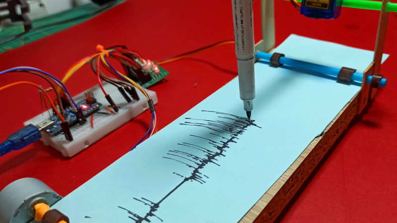
We always love to see projects where you can build your own lab equipment so [CompactDIY’s] homemade seismograph caught our eye. The design uses an Arduino with an accelerometer and builds on one of their earlier projects. You can see a video of the device below.

The principle is simple. A hobby servo controls a pen and a stepper motor rolls paper, creating a makeshift strip recorder. Its software uses the Visuino system, which is a flowchart-like system, but it outputs Arduino code. Honestly, we would probably have just plotted the data on a PC, but there’s a certain charm to the strip recorder and the idea would work for other types of data recording projects, too. We thought if you rearranged the stepper motor and cut a paper disk out, you could also have a circular chart recorder easily, which wouldn’t need to friction transport the paper. A clock motor would make it even less dependent on software, too.

If this project interests you, try a Raspberry shake, which isn’t as delicious as it sounds. Or, keep an eye on the entire globe, if you prefer.

Ever wanted your own gesture-controlled robot arm? [EbenKouao]’s DIY Arduino Robot Arm project covers all the bases involved, but even if a robot arm isn’t your jam, his project has plenty to learn from. Every part is carefully explained, complete with source code and a list of required hardware. This approach to documenting a project is great because it not only makes it easy to replicate the results, but it makes it simple to remix, modify, and reuse separate pieces as a reference for other work.

[EbenKouao] uses a 3D-printable robotic gripper, base, and arm design as the foundation of his build. Hobby servos and a single NEMA 17 stepper take care of the moving, and the wiring and motor driving is all carefully explained. Gesture control is done by wearing an articulated glove upon which is mounted flex sensors and MPU6050 accelerometers. These sensors detect the wearer’s movements and turn them into motion commands, which in turn get sent wirelessly from the glove to the robotic arm with HC-05 Bluetooth modules. We really dig [EbenKouao]’s idea of mounting the glove sensors to this slick 3D-printed articulated gauntlet frame, but using a regular glove would work, too. The latest version of the Arduino code can be found on the project’s GitHub repository.

Most of the parts can be 3D printed, how every part works together is carefully explained, and all of the hardware is easily sourced online, making this a very accessible project. Check out the full tutorial video and demonstration, embedded below.

3D printing has been a boon for many projects, especially those involving robotic arms. All kinds of robotic arm projects benefit from the advantages of 3D printing, from designs that focus on utility and function, to clever mechanical designs that reduce part count in unexpected ways.

A spirit level, you know the kind of level with a little bubble in a tube of fluid, is a basic construction tool. [DesignBuildDestroy] took an Arduino, a gyroscope chip, and an OLED, and made a 3D printed level with no bubble, but it does have a nice digital display.

It is funny when you realize that at one time a gyroscope was a high tech item reserved for missiles and aircraft. Now you can grab a six-axis sensor for pennies. Even, better, the code used in the project can offload the Arduino for a lot of processing.

Initially, the device lived on a breadboard, which is always a good idea to get the kinks out of things. Thanks to the OLED, the Arduino can calibrate itself without a PC and do other tricks. The display is easy to read, but we thought there should be a mode that shows a little bubble made with an O character. Seems like that would be a fun rainy day project. We did like the automatic screen rotation, though.

We’ve seen a nice level done with a Raspberry Pi before. If you need something smaller, how about something the size of a dime?

We suppose it’s a bit early to call it just yet, but we definitely have a solid contender for Father of the Year. [DIY_Maxwell] made a light-up hockey game for his young son that looks like fun for all ages. Whenever the puck is hit with the accompanying DIY hockey stick (or anything else), it lights up and produces different sounds based on its acceleration.

Inside the printed puck is an Arduino Nano running an MPU6050 accelerometer, a 12-NeoPixel ring, and a piezo buzzer. [DIY_Maxell] reused a power bank charging circuit to charge up the small LiPo battery.

The original circuit used a pair of coin cells, but the Arduino was randomly freezing up, probably because of the LEDs’ current draw. Be sure to check out the video after the break, which begins with a little stop motion and features a solder stand in the shape of a 3D printer.

Got a house full of carpet or breakables? You could always build an air hockey table instead.

When you’re a kid, remote control cars are totally awesome. Even if you can’t go anywhere by yourself, it’s much easier to imagine a nice getaway from the daily grind of elementary school if you have some wheels. And yeah, R/C cars are still awesome once you’re an adult, but actual car-driving experience will probably make you yearn for more realism.

What could be more realistic and fun than an active suspension? Plenty of adults will never get the chance to hit the switches in real car, but after a year of hard work, [snoopybg] is ready to go front and back, side to side, and even drift in this super scale ’63 Oldsmobile Dynamic 88 wagon. We think you’ll agree that [snoopybg] didn’t miss a detail — this thing makes engine noises, and there are LEDs in the dual exhaust pipes to simulate flames.

An Arduino reads data from a triple-axis accelerometer in real time, and adjusts a servo on each wheel accordingly, also in real time, to mimic a real car throwing its weight around on a real suspension system. If that weren’t cool enough, most of the car is printed, including the tires. [snoopybg] started with a drift car chassis, but even that has been hacked and drilled out as needed.

There are a ton of nice pictures on [snoopybg]’s site if you want to see what’s under the hood. We don’t see the code anywhere, but [snoopybg] seems quite open to publishing more details if there is interest out there. Strap yourself in and hold on tight, because we’re gonna take this baby for a spin after the break.

If this is all seems a bit much for you, but you’ve got that R/C itch again, there’s a lot to be said for upgrading the electronics in a stock R/C car.

Via r/duino

In the distant past, engineers used exotic devices to measure orientation, such as large mechanical gyros and mercury tilt switches. These are all still useful methods, but for many applications MEMS motions devices have become the gold standard. When [g199] set out to build their Balance Box game, it was no exception.

The game consists of a plastic box, upon which a spirit level is fitted, along with a series of LEDs. The aim of the game is to keep the box level while carrying it to a set goal. Inside, an Arduino Uno monitors the output of a MPU 6050, a combined accelerometer and gyroscope chip. If the Arduino detects the box is tilting, it warns the user with the LEDs. Tilt it too far, and a life is lost. When all three lives are gone, the game is over.

It’s a cheap and simple build that would have been inordinately more expensive only 10 to 20 years ago. It goes to show the applications enabled by ubiquitous cheap electronics like MEMS sensors. The technology has other fun applications, too – for example the Stecchino game, or this giant balance board joystick. We’re certainly lucky to have such powerful technology at our fingertips!

[James Bruton], from the XRobots YouTube channel is known for his multipart robot and cosplay builds. Occasionally, though, he creates a one-off build. Recently, he created a video showing how to build a LED ball that changes color depending on its movement.

The project is built around a series of 3D printed “arms” around a hollow core, each loaded with a strip of APA102 RGB LEDs. An Arduino Mega reads orientation data from an MPU6050 and changes the color of the LEDs based on that input. Two buttons attached to the Mega modify the way that the LEDs change color. The Mega, MPU6050, battery and power circuitry are mounted in the middle of the ball. The DotStar strips are stuck to the outside of the curved arms and the wiring goes from one end of the DotStar strip, up through the middle column of the ball to the top of the next arm. This means more complicated wiring but allows for easier programming of the LEDs.

Unlike [James’] other projects, this one is a quickie, but it works as a great introduction to programming DotStar LEDs with an Arduino, as well as using an accelerometer and gyro chip. The code and the CAD is up on Github if you want to create your own. [James] has had a few of his projects on the site before; check out his Open Dog project, but there’s also another blinky ball project as well.

Nov
22

Building a self balancing bot

Accelerometer, arduino, ATmega, ATmega328, Bajduino, IMU, motor, MPU6050 Comments Off on Building a self balancing bot 

self-balancing-bot-1-600x400

Bajdi documented his Arduino self balancing bot build:

For the electronics I used one of my own PCB creations, a Bajduino of course It’s just a small (50x50mm) break out board for an ATmega328. I’m running the ATmega @ 16MHz and 3.3V. It’s out of spec according to the datasheet but it works… I also needed an IMU of course. I found a MP6050 sensor in my parts box. The MPU6050 combines a 3 DOF gyro and 3 DOF accelerometer in a small package, ideal for a self balancing bot.

[via]

Building a self balancing bot - [Link]


  • Newsletter

    Sign up for the PlanetArduino Newsletter, which delivers the most popular articles via e-mail to your inbox every week. Just fill in the information below and submit.

  • Like Us on Facebook