I fell into an internet search rabbit hole and came across ‘Drag Racing’ start lights. I had seen references to these on the Arduino forum and they looked interesting enough, and followed well defined rules, to be a relatively simple project for programming practice.
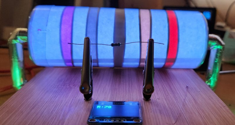
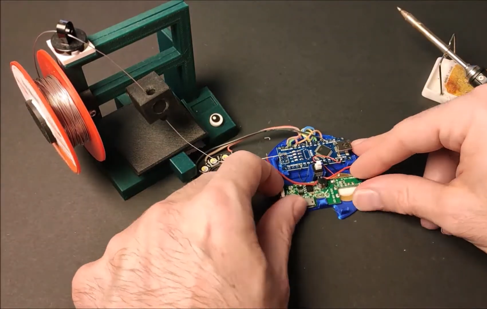
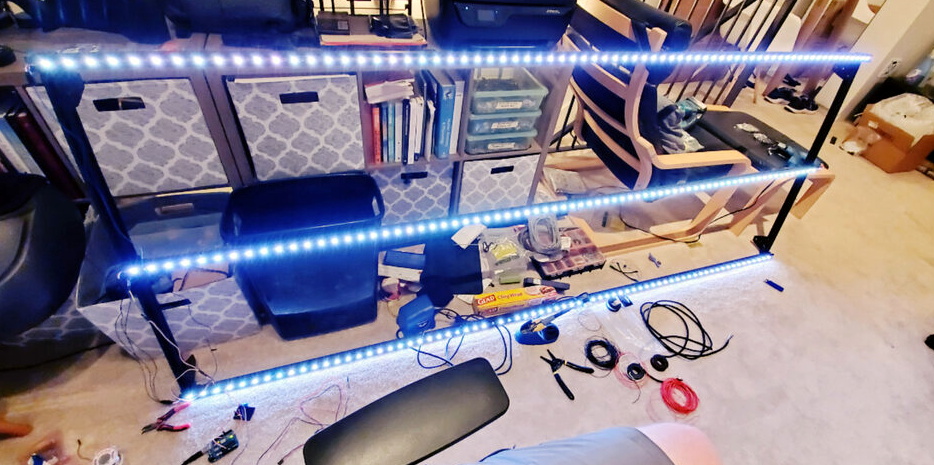
Here’s the result from an afternoon of tinkering.
How do these start lights work?
Drag races are started electronically by a system known as a Christmas tree. A common Christmas tree consists of a column of seven lights for each driver or lane, as well as a set of light beams across the track itself. The light beams are arranged with one set on the starting line, and another set 7 inches behind it.
Each side of the column of lights is the same from the top down:
- two blue/white/yellow (it seems to vary) lamps at the top
- three amber/yellow lamps
- one green lamp
- one red lamp
When drivers are preparing to race, they first cross the beams 7 inches behind the starting line. Crossing this beam put the race in pre-staged mode and activates the top bulbs. At this point the tree is activated.
Once pre-staged, drivers roll up 7 inches and cross the second beam on the starting line. Once the first driver activates the bottom (staged) bulbs, the subsequent drivers have 7 seconds to do the same or they are timed out and automatically disqualified.
Once all drivers have crossed the staged sensor, or are timed out, the starting system activates the amber lighting sequence within 1.3 seconds of the last car being staged or being disqualified. The lighting sequence will be different based on the type of tree and race start being used:
- A Standard tree lights up each amber light in sequence with a 500 millisecond (ms) delay between them, followed by the green light after another 500 ms delay.
- A Professional tree lights up all the amber lights at the same time, followed by the green light after a 400 ms delay.
- A Hybrid (or Professional 500) tree, is the same as a professional tree with a 500 ms delay before the green light.
On the activation of the green light the drivers are supposed to start the race.
Leaving the “Staged” line before the green light activates will instantly stop the count down and result in a lighting of the red light and a provisional disqualification of the offending driver.
Software Design
There are 2 things that we need to keep track of for this project.
The first is the racer or racing lane (these are one-to-one so I consider them equivalent). Each race has a number of lanes (usually 2 but in our world potentially more). A lane has a digital device (digital input for us) to show that the vehicle is staged and a similar device to show when the vehicle moves past the start line. A lane/racer also has the attributes of being in a staged and/or foul state.
The second is the set of lights. Each lane has one or more start light trees associated with that lane. There is always one light tree facing the racer but there could be more for crowd/officials. A light tree therefore has an association with a racer and the appropriate lighting circuits.
The logic to progress the lighting sequence is simple to implement as a Finite State Machine that follows the process description above. In my case I also wanted to capture Standard, Professional and Hybrid operating modes within the same code base.
Hardware Implementation
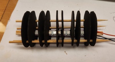
The first decision for the hardware is to decide how the software will be used. I decided that the software was probably most likely to be used for model or radio-controlled cars, so Neopixel (serial RGB) LEDs can be used allowing the system to be implemented with relatively low power requirements. The code logic is, obviously, scalable to larger systems if required by changing the output hardware.
For simplicity I also assumed that digital inputs provide the necessary signals for staging and foul condition. A simple digital is also used as a control to restart the lights sequence. During testing all these digital signals were connected to tact switches.
Software Implementation
The full sketch for this project is available at my code repository.
The first thing to define are the racer and light tree data structures as they form the basis for the rest of the code.
The oneTree_t type defines a tree of lights. The set of neopixel LEDs for a tree is assumed to be consecutive and similar (ie, same order) for all trees. This means that we just need to keep track of the base LED number for each tree and the rest are standard offsets from this base.
// Define the offsets from base for each set of lights
const uint8_t idStaging = 0;            // Staging LED
const uint8_t idStaged = 1;             // Staged LED
const uint8_t idReady[3] = { 2, 3, 4 }; // Ready LED (yellow)
const uint8_t idGo = 5;                 // Go LED (green)
const uint8_t idFoul = 6;               // Fould LED (red)

const uint8_t LED_PER_TREE = 7;         // LEDS in each tree

// Define what we need to keep track of for one tree of lamps
struct oneTree_t
{
  uint8_t idRacer;    // 0 .. NUM_RACERS-1. Racer's tree.
  uint8_t idLEDBase;  // The first led number for this tree
};

// Define the data for all the lamp trees required
// There are only 2 types of trees (one per racer) but these
// may be displayed multiple times (eg, front and back of a
// column, around the park, etc).
// This array defines the number of trees required, which
// racers they 'belong' to and the starting neopixel address
// for the LED_PER_TREE leds for this tree.
// Altogether this is the total number of LEDS that the
// FastLED software has to manage.
oneTree_t display[] =
{
  { 0, 0 },
  { 1, LED_PER_TREE * 1 },
  { 0, LED_PER_TREE * 2 },
  { 1, LED_PER_TREE * 3 },
};
The oneRacer_t type groups the data related to one racer. Input pins are defined for the ‘staged’ and ‘fault’ inputs, and booleans keep track of the staged and foul conditions.
// Define what we need to keep track of for one racer
struct oneRacer_t
{
  uint8_t pinStaged;  // input pin indicates staged when low
  uint8_t pinFoul;    // input pin indicates foul when low
  bool isStaged;      // true if the racer is staged
  bool isFoul;        // true if tree is showing foul
};

// Define the data for all the racers
// One line entry per racer. There are normally only 2
// racers in a drag race but more can be defined if required
// without changes to the software.
oneRacer_t racer[] =
{
  { 4, 5, false, false },
  { 6, 7, false, false },
};

// Derive global constants from this array definition
const uint8_t NUM_RACERS = ARRAY_SIZE(racer);
The different operating modes are implemented through timing differences and some minor code variation. The software will compile to operate in any of the three modes by using the compile time #define TREE_MODE.
// Define the running mode for the tree
// Set 0 = Standard, 1 = Professional or 2 = Hybrid
#ifndef TREE_MODE
#define TREE_MODE 0
#endif

// Set up parameters for different modes
#if TREE_MODE == 0  // Standard Mode
#warning "Compiling for STANDARD TREE"

const uint32_t STAGE_DELAY = 7000; // in milliseconds
const uint32_t READY_DELAY = 1300; // in milliseconds
const uint32_t SET_DELAY = 500;    // in milliseconds
const uint32_t GO_DELAY = 500;     // in milliseconds

#elif TREE_MODE == 1  // Professional Mode
#warning "Compiling for PROFESSIONAL TREE"

const uint32_t STAGE_DELAY = 7000; // in milliseconds
const uint32_t READY_DELAY = 1300; // in milliseconds
const uint32_t SET_DELAY = 0;      // in milliseconds
const uint32_t GO_DELAY = 400;     // in milliseconds

#elif TREE_MODE == 2  // Hybrid Mode
#warning "Compiling for HYBRID TREE"

const uint32_t STAGE_DELAY = 7000; // in milliseconds
const uint32_t READY_DELAY = 1300; // in milliseconds
const uint32_t SET_DELAY = 0;      // in milliseconds
const uint32_t GO_DELAY = 500;     // in milliseconds

#endif
The bulk of the controlling code is in the loop() function, which is a Finite State Machine implemented in a case statement with the following cases defined:
  static enum {
    RESET,        // reset variables for next run
    PRE_STAGE,    // wait for signal to enable tree
    STAGING,      // wait for all lanes to stage or time out
    WAIT_START,   // delay before start sequence
    START_READY,  // yellow light sequence
    START_SET,    // delay before green
    START_GO,     // set green light
    WAIT_RESET,   // sequence ended, waiting for signal to reset
  } curState = RESET;