Posts | Comments

Planet Arduino

Archive for the ‘hall effect sensor’ Category

A shot of the underside of a "One Fast Cat" cat wheel with an installed ESP8266 and hall effect sensors attached to the base.

[Scott Cutler] has a young cat, [Cygnus], that loves to run on a cat wheel and [Scott] had some some important questions about [Cygnus]’s usage of the cat wheel like, how often it’s used, what direction is preferred and how fast does [Cygnus] go. To answer these questions, [Scott] put some telemetry sensors onto the cat wheel and analyzed the results.

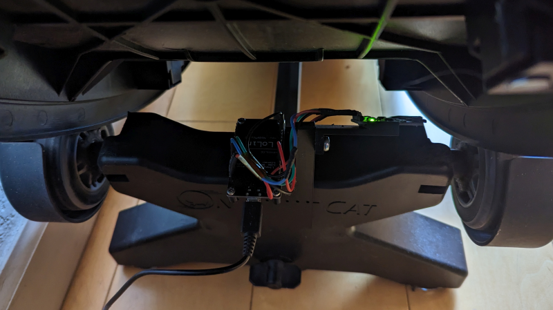
An ESP8266 microcontroller and two 3144E hall effect modules were used to sense eight magnets glued onto the outer housing of a “One Fast Cat” cat wheel. [Scott] installed the ESP8266 and hall effect modules onto the base support for the wheels, using 3D printed brackets to secure them.

For the software side, the ESP8266 attaches an interrupt handler whenever a sensor passes by, recording a window of three previous measurements for valid sample determination and, if accepted, uses the time between samples to infer direction and speed. The ESP8266 connects to a pre-configured local WiFi network and has a telnet interface to extract stored log information, in the form of JSON data.

[Scott] has some nice graphs and other data visualizations on [Cygnus]’s usage, including a preference for running at 3 AM, achieving a maximum speed of 14 mph and an average of 4 seconds per run. The source is available on GitHub and the STL files are available embedded in [Scott]’s write-up. We’ve featured cat exercise trackers before with a giant hamster wheel outfitted with a Raspberry Pi and it’s nice to see some options that allow for a retrofit option in addition to a complete DIY solution.

We’re used to Hall effect devices as proximity sensors in mechanical systems, used to provide detection of something that has a magnet attached to it. However it’s easy to forget that the devices that provide a magnet-or-not digital output are only part of the story, and linear Hall effect devices provide a handy way to measure a static magnetic field. It’s something [mircemk] demonstrates, with an Arduino-powered magnetic field strength meter that uses a UGN 3503U Hall effect device.

The circuit is extremely simple, comprising the sensor, an Arduino Nano, and an OLED display. This device is handy because its voltage output has a known relationship to the gauss level the sensor is experiencing, so while the accuracy of its calibration isn’t verified it can at least give a believable reading derived from the Arduino’s ADC.

The whole is wrapped up in an attractive case that looks as though it has been made from PCB material, with the sensor protruding on what seems to be the shell of a plastic ballpoint pen. It makes a handy instrument that provides a useful function for not a lot of money, so what’s not to like! Take a look at the video below the break for the full story.

Surprisingly such projects are few and far between here at Hackaday, however it’s not the first magnetic field measurement we’ve seen.

We have seen quite a few DIY joystick designs that use Hall effect sensors, but [Akaki]’s controller designs (YouTube video, embedded below) really make the most of 3D printing to avoid the need for any other type of fabrication. He’s been busy using them to enhance his Microsoft Flight Simulator 2020 experience, and shares not just his joystick design, but makes it a three-pack with designs for throttle and pedals as well.

Hall effect sensors output a voltage that varies in proportion to the presence of a magnetic field, which is typically provided by a nearby magnet. By mounting sensors and magnets in a way that varies the distance between them depending on how a control is moved, position can be sensed and communicated to a host computer. In [akaki]’s case, that communication is done with an Arduino Pro Micro (with ATmega32U4) whose built-in USB support allows it to be configured and recognized as a USB input device. The rest is just tweaking the physical layouts and getting spring or elastic tension right. You can see it all work in the video below.

Hall effect sensors have featured in DIY joystick builds, but for something as delightful as it is different, don’t miss this fantastic high-speed magnetic imager based on them.

Laundry. It’s one of life’s inescapable cycles, but at least we have machines now. The downside of this innovation is that since we no longer monitor every step — the rock-beating, the river-rinsing, the line-hanging and -retrieving — the pain of laundry has evolved into the monotony of monitoring the robots’ work.

[Adam] shares his wash-bots with roommates, and they aren’t close enough to combine their lights and darks and turn it into a group activity. They needed an easy way to tell when the machines are done running, and whose stuff is even in there in the first place, so [Adam] built a laundry machine monitor that uses current sensing to detect when the machines are done running and sends a text to the appropriate person.

Each machine has a little Hall effect-sensing module that’s carefully zip-tied around its power cable. The signal from these three-wire boards goes high when the machine is running and low when it’s not. At the beginning of the load, the launderer simply presses their assigned button on the control box, and the ESP32 inside takes care of the rest.

Getting a text when your drawers are clean is about as private as it gets. Clean underwear, don’t care? Put it on a scrolling marquee.

Timepieces are cool no matter how simplistic or granular they are. Sometimes its nice not to know exactly what time it is down to the second, and most of the really beautiful clocks are simple as can be. If you didn’t know this was a clock, it would still be fascinating to watch the bearings race around the face.

This clock takes design cues from the Story clock, a visual revolution in counting down time which uses magnetic levitation to move a single bearing around the face exactly once over a duration of any length as set by the user. As a clock, it’s not very useful, so there’s a digital readout that still doesn’t justify the $800 price tag.

[tomatoskins] designed a DIY version that’s far more elegant. It has two ball bearings that move around the surface against hidden magnets — an hour ball and a minute ball. Inside there’s a pair of 3D-printed ring gears that are each driven by a stepper motor and controlled with an Arduino Nano and a real-time clock module. The body is made of plywood reclaimed from a bed frame, and [tomatoskins] added a walnut veneer for timeless class.

In addition to the code, STLs, and CAD files that birthed the STLs, [tomatoskins] has a juicy 3D-printing tip to offer. The gears had to be printed in interlocked pieces, but these seams can be sealed with a solution of acetone and plastic from supports and failed prints.

If you dig minimalism but think this clock is a bit too vague to read, here’s a huge digital clock made from small analog clocks.

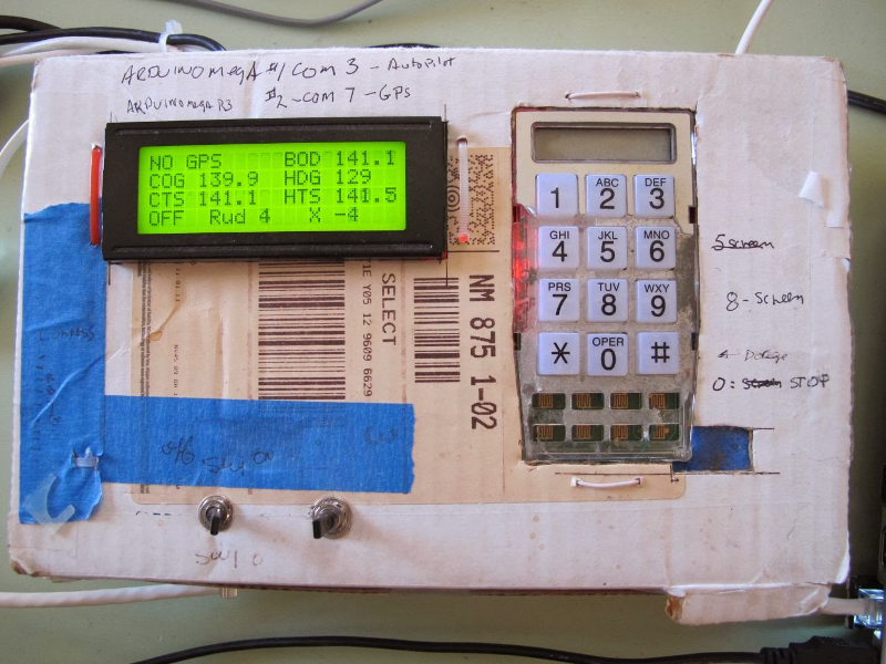
[Jack], a mechanical engineer, loom builder, and avid sailor wanted an autopilot system for his 1983 Robert Perry Nordic 40 sailboat with more modern capabilities than the one it came with. He knew a PC-based solution would work, but it was a bit out of reach. Once his son showed him an Arduino, though, he was on his way. He sallied forth and built this Arduino-based autopilot system for his sloop, the Wile E. Coyote.

He’s using two Arduino Megas. One is solely for the GPS, and the other controls everything else. [Jack]‘s autopilot has three modes. In the one he calls knob steering, a potentiometer drives the existing hydraulic pump, which he controls with a Polulu Qik serial DC motor controller. In compass steering mode, a Pololu IMU locks in the heading to steer (HTS).  GPS mode uses a predetermined waypoint, and sets the course to steer (CTS) to the same bearing as the waypoint.

[Jack]‘s system also uses cross track error (XTE) correction to calculate a new HTS when necessary. He has fantastic documentation and several Fritzing and Arduino files available on Dropbox.

Autopilot sailboat rigs must be all the rage right now. We just saw a different one back in November.

[Thanks Jeremy]


Filed under: Arduino Hacks, gps hacks, misc hacks, transportation hacks


  • Newsletter

    Sign up for the PlanetArduino Newsletter, which delivers the most popular articles via e-mail to your inbox every week. Just fill in the information below and submit.

  • Like Us on Facebook