Thermal cameras are very useful tools, because they let us see heat that would normally be invisible to our eyes. Maybe you’re working on a custom PCB and want to see if any of the components generate excessive heat. Or maybe you’re concerned that your car’s exhaust headers don’t heat evenly and you want to see what’s going on. Thermal cameras tend to be expensive, but Vaclav Krejci (AKA upir on YouTube) has a video that explains how you can build your own low-resolution thermal camera without breaking the bank.
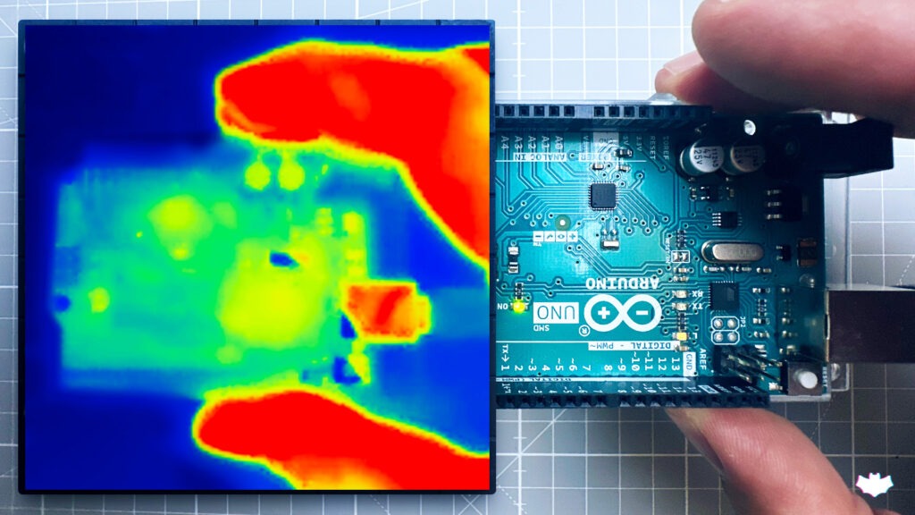
Krejci’s design only has an 8×8 resolution, which is the maximum native output of the AMG8833 infrared sensor array. By conventional digital camera standards, that is too low to be usable. But it is enough for some simple tasks you might want to perform with a thermal camera. At that resolution, the device will act almost like a non-contact thermometer that shows you 64 points. You can identify hot IC chips and even see large thermal currents.
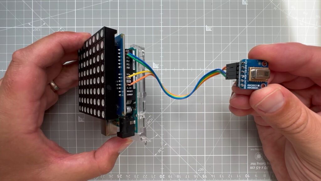
The only components you need to replicate Krejci’s design are an Arduino UNO Rev3 board, an AMG8833 infrared sensor module, and an 8×8 RGB LED matrix (Krejci used a Sunfounder model). The sketch gathers the 64 values from the infrared sensor and then uses those to set the hue of each pixel in the LED matrix. The Colorduino library lets you set pixel colors using the HSV (hue, saturation, value) model, which makes it easy to change the color by adjusting the hue of each pixel.
The result is an LED display that shows a heat map, with cool areas being blue and very hot areas being red. The resolution is low, but each pixel has decent precision.
If you have any kind of business, chances are it involves stickers at some point in the process. More accurately it involves you peeling the backs off of sticker after sticker, slowly wasting time and working your way toward a repetitive stress injury. Why do that to yourself when you could have a machine do it for you?
That’s exactly the thinking behind [Mr Innovative]’s automatic label dispensing machine. All he has to do is load up the roll of labels, dial in the length of each label, and away the machine goes, advancing and dispensing and taking up the empty paper all at once. In fact, that’s how it works: the take-up reel is on the shaft of a NEMA-17 stepper motor, which gets its instructions from an Arduino Nano and an A4988 motor driver. Our favorite part is the IR sensor located underneath the sticker that’s ready to take — the machine doesn’t feed another until it senses that you’ve taken the previous sticker. We stuck the demo and build video after the break.
Our other favorite thing about this build is that [Mr Innovative] seems to have used the same PCB as his freaky fast bobbin winder.
The traditional theremin is more or less an audio oscillator with two metal rods. Using proximity sensing, one rod controls the pitch of the oscillator and the other controls the volume. [Teodor Costachiou] apparently asked himself the excellent question: Why does the proximity sensor have to use capacitance? The result is an Arduino-based theremin that uses IR sensors to determine hand position.
[Teodor] used a particular type of Arduino–the Flip and Click–because he wanted to use Click boards for the IR sensors and also to generate sound via an MP3 board based around a VS1053. The trick is that the VS1053 has a realtime MIDI mode, and that’s how this Theremin makes it tones.
Of course, a real theremin is distinctly analog. A tiny change in hand position creates a small change in the output. With digital sensors and sound generation, the output is more in discrete steps, but according to [Teodor], the effect isn’t bad. We were hoping for a video (or, at least, an audio clip) but [Teodor] pleaded that he’s not a musician. He did include a video of a real theremin performance with his post, and you can see it below. But that’s a real analog theremin.
If you want to build something more traditional, have a look at Open Theremin. Or, if you want to get your exercise, how about trying a terpsitone. If you do, and can play the theme to The Day the Earth Stood Still, we’d love to see the video. Meanwhile, if you didn’t know the theremin had an espionage connection, you haven’t been staying current on Hackaday posts.
This is a repost of a previous project. I am still working to get the older post back online from when we upgraded Wordpress.
The robot was basically built using a Parallax Boe Bot chassis. Rather than using the Basic Stamp we added an Arduino with a proto shield to control the robot functions.
You can use any type of chassis for this project. The robot moves about using a ping sonar and IR sensors to avoid running into any objects. As you can see in the video, it was a bit thrown off by our kitten. We added additional items such as a wireless camera that sends audio/video back to our TV.The original design for this was created by an Instructable’s member and can be found here.
The standard servo will be used to mount the Ping Rangefinder. This will give you a back and forth sweep motion as the robot travels around. The two continuous rotation servos are used for the wheels. You do not need to use the Parallax brand of servos, other brands will work. You may have to adjust the PWM values in the source code to go with the servos you are using.
The Arduino hook up is pretty simple. You will have the following:
Pin (Analog) 0: Left Sensor
Pin (Analog) 1: Center Sensor
Pin (Analog) 2: Right Sensor
Pin 5: Pan Servo
Pin 6: Left Drive Servo
Pin 7: Ultrasonic Rangefinder ( ‘Ping)))’ )
Pin 9: Right Drive Servo
Pin 11: Piezo Speaker
Shield Close-up
Radioshack sells an RC car battery as well as connector repair kit. You can solder the repair kit connector onto the shield, and then be able to hook up your battery to power the servos with. You can use a separate battery holder to power the Arduino.
Make all your connections onto the shield. This way everything can remain in place if you need to use your Arduino for something else and save you from needing to tear apart everything.
for power to the shield, you won’t need any extra filter capacitors since the 5V switching regulator has them built in. We used a small project box to hold the battery in place, and was able to attach the wireless camera on top of it.
The Arduino and camera are power source 1, while the servos and sensors are power source 2 (the RC battery). A small piece of PVC pipe mounted onto a cable clip will help you to keep your wires all organized to a central point and be less likely to get caught or tangled up into something as the robot is moving around.
Arduino Sketch
// Begin Robot Codeint micVal;
int cdsVal;
int irLval; // Left IRint irCval; // Center IRint irRval; // Right IRint i; // Generic Counterint x; // Generic Counterint PLval; // Pulse Width for Left Servoint PRval; // Pulse Width for Right Servoint cntr; // Generic Counter Used for Determining amt. of Object Detectionsint counter; // Generic Counterint clrpth; // amt. of Milliseconds Of Unobstructed Pathint objdet; // Time an Object was Detectedint task; // Routine to Follow for Clearest Pathint pwm; // Pulse Width for Pan Servoboolean add; // Whether to Increment or Decrement PW Value for Pan Servoint distance; // Distance to Object Detected via Ultrasonic Rangerint oldDistance; // Previous Distance Value Read from Ultrasonic Rangerfloat scale = 1.9866666666666666666666666666667; // *Not Currently Used*int LeftPin = 6; // Left Servoint RightPin = 9; // Right Servoint PiezoPin = 11; // Piezoint PingServoPin = 5; // Pan Servoint irLPin = 0; // Analog 0; Left IRint irCPin = 1; // Analog 1; Center IRint irRPin = 2; // Analog 2; Right IRint ultraSoundSignal = 7; // Ultrasound signal pinint val = 0; // Used for Ultrasonic Rangerint ultrasoundValue = 0; // Raw Distance Valint oldUltrasoundValue; // *Not used*int pulseCount; // Generic Counterint timecount = 0; // Echo counterint ledPin = 13; // LED connected to digital pin 13
#define BAUD 9600
#define CmConstant 1/29.034
voidsetup() {
Serial.begin(9600);
pinMode(PiezoPin, OUTPUT);
pinMode(ledPin, OUTPUT);
pinMode(LeftPin, OUTPUT);
pinMode(RightPin, OUTPUT);
pinMode(PingServoPin, OUTPUT);
pinMode(irLPin, INPUT);
pinMode(irCPin, INPUT);
pinMode(irRPin, INPUT);
for(i = 0; i < 500; i++) {
digitalWrite(PiezoPin, HIGH);
delayMicroseconds(1000);
digitalWrite(PiezoPin, LOW);
delayMicroseconds(1000);
}
for(i = 0; i < 20; i++) {
digitalWrite(PingServoPin, HIGH);
delayMicroseconds(655 * 2);
digitalWrite(PingServoPin, LOW);
delay(20);
}
ultrasoundValue = 600;
i = 0;
}
voidloop()
{
//Scan();
Look();
Go();
}
void Look() {
irLval = analogRead(irLPin);
irCval = analogRead(irCPin);
irRval = analogRead(irRPin);
//if(counter > 10) {//counter = 0;//readPing();//}if(irLval > 200) {
PLval = 850;
PRval = 820;
x = 5;
cntr = cntr + 1;
clrpth = 0;
objdet = millis();
}
elseif(irCval > 200) {
PLval = 850;
PRval = 820;
x = 10;
cntr = cntr + 1;
clrpth = 0;
objdet = millis();
}
elseif(irRval > 200) {
PLval = 650;
PRval = 620;
x = 5;
cntr = cntr + 1;
clrpth = 0;
objdet = millis();
}
else {
x = 1;
PLval = 850;
PRval = 620;
counter = counter + 1;
clrpth = (millis() - objdet);
if(add == true) {
pwm = pwm + 50;
}
elseif(add == false) {
pwm = pwm - 50;
}
if(pwm < 400) {
pwm = 400;
add = true;
}
if(pwm > 950) {
pwm = 950;
add = false;
}
digitalWrite(PingServoPin, HIGH);
delayMicroseconds(pwm * 2);
digitalWrite(PingServoPin, LOW);
delay(20);
readPing();
if(ultrasoundValue < 500) {
cntr = cntr + 1;
switch(pwm) {
case 400:
x = 7;
PLval = 650;
PRval = 650;
Go();
break;
case 500:
x = 10;
PLval = 650;
PRval = 650;
Go();
break;
case 600:
x = 14;
PLval = 850;
PRval = 850;
Go();
break;
case 700:
x = 10;
PLval = 850;
PRval = 850;
Go();
break;
case 950:
x = 7;
PLval = 850;
PRval = 850;
Go();
break;
}
}
}
//Serial.print("clrpth: ");//Serial.println(clrpth);//Serial.print("objdet: ");//Serial.println(objdet);//Serial.print("cntr: ");//Serial.println(cntr);if(cntr > 25 && clrpth < 2000) {
clrpth = 0;
cntr = 0;
Scan();
}
}
void Go() {
for(i = 0; i < x; i++) {
digitalWrite(LeftPin, HIGH);
delayMicroseconds(PLval * 2);
digitalWrite(LeftPin, LOW);
digitalWrite(RightPin, HIGH);
delayMicroseconds(PRval * 2);
digitalWrite(RightPin, LOW);
delay(20);
}
}
void readPing() { // Get Distance from Ultrasonic Ranger
timecount = 0;
val = 0;
pinMode(ultraSoundSignal, OUTPUT); // Switch signalpin to output/* Send low-high-low pulse to activate the trigger pulse of the sensor * ------------------------------------------------------------------- */digitalWrite(ultraSoundSignal, LOW); // Send low pulsedelayMicroseconds(2); // Wait for 2 microsecondsdigitalWrite(ultraSoundSignal, HIGH); // Send high pulsedelayMicroseconds(5); // Wait for 5 microsecondsdigitalWrite(ultraSoundSignal, LOW); // Holdoff/* Listening for echo pulse * ------------------------------------------------------------------- */pinMode(ultraSoundSignal, INPUT); // Switch signalpin to input
val = digitalRead(ultraSoundSignal); // Append signal value to valwhile(val == LOW) { // Loop until pin reads a high value
val = digitalRead(ultraSoundSignal);
}
while(val == HIGH) { // Loop until pin reads a high value
val = digitalRead(ultraSoundSignal);
timecount = timecount +1; // Count echo pulse time
}
/* Writing out values to the serial port * ------------------------------------------------------------------- */
ultrasoundValue = timecount; // Append echo pulse time to ultrasoundValue//serialWrite('A'); // Example identifier for the sensor//printInteger(ultrasoundValue);//serialWrite(10);//serialWrite(13);/* Lite up LED if any value is passed by the echo pulse * ------------------------------------------------------------------- */if(timecount > 0){
digitalWrite(ledPin, HIGH);
}
}
void Scan() { // Scan for the Clearest Path
oldDistance = 30;
task = 0;
for(i = 1; i < 5; i++) {
switch(i) {
case 1:
//Serial.println("Pos. 1");
pwm = 1125; /// incr. by 100 from 1085
break;
case 2:
//Serial.println("Pos. 2");
pwm = 850; //// increased by 100 from 850
break;
case 3:
//Serial.println("Pos. 3");
pwm = 400;
break;
case 4:
//Serial.println("Pos. 4");
pwm = 235;
break;
}
for(pulseCount = 0; pulseCount < 20; pulseCount++) { // Adjust Pan Servo and Read USRdigitalWrite(PingServoPin, HIGH);
delayMicroseconds(pwm * 2);
digitalWrite(PingServoPin, LOW);
readPing();
delay(20);
}
distance = ((float)ultrasoundValue * CmConstant); // Calculate Distance in Cmif(distance > oldDistance) { // If the Newest distance is longer, replace previous reading with it
oldDistance = distance;
task = i; // Set task equal to Pan Servo Position
}
}
//Serial.print("Task: ");//Serial.println(task);//Serial.print("distance: ");//Serial.println(distance);//Serial.print("oldDistance: ");//Serial.println(oldDistance);
distance = 50; // Prevents Scan from Loopingswitch(task) { // Determine which task should be carried outcase 0: // Center was clearest
x = 28;
PLval = (850);
PRval = (850);
Go();
break;
case 1: // 90 degrees Left was Clearest
x = 14;
PLval = (650);
PRval = (650);
Go();
break;
case 2: // 45 degrees left
x = 7;
PLval = (650);
PRval = (650);
Go();
break;
case 3: // 45 degrees right
x = 7;
PLval = (850);
PRval = (850);
Go();
break;
case 4: // 90 degrees right
x = 14;
PLval = (850);
PRval = (850);
Go();
break;
}
}
// End Robot Code
About
Planet Arduino is, or at the moment is wishing to become, an aggregation of public weblogs from around the world written by people who develop, play, think on Arduino platform and his son. The opinions expressed in those weblogs and hence this aggregation are those of the original authors. Entries on this page are owned by their authors. We do not edit, endorse or vouch for the contents of individual posts. For more information about Arduino please visit www.arduino.cc
You are currently browsing the archives for the IR Sensor category.