Posts | Comments

Planet Arduino

Archive for the ‘i2c’ Category

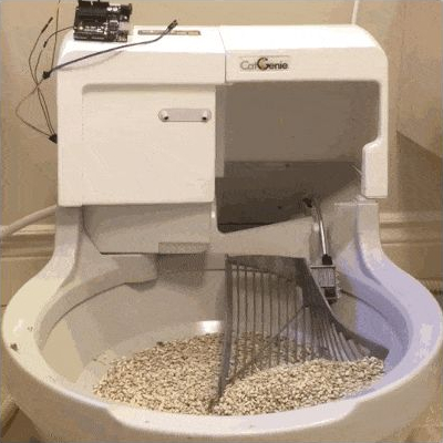
The CatGenie is an amazing device to watch in action, basically a self-cleaning litter box for cats that even does away with the need to replace the litter. It’s comparable to what the indoor flush toilet is for humans compared to maintaining a composting toilet. However, there is a problem. It uses costly soap cartridges which have to be replaced because an RFID reader and a usage counter prevent you from simply refilling them yourself.

CatGenie and Arduino

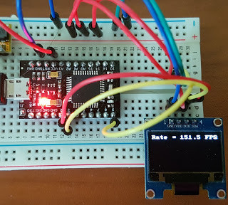
[David Hamp-Gonsalves] reverse engineered the electronics so that he didn’t have to pay for the cartridges anymore. This has been done before and one of those who did it created a product called the CartridgeGenius, but it’s made and sold as a parttime project and there were none in stock. The cartridges have an RFID tag and another solution which we’ve covered before is to replace the RFID reader board with an Arduino. That’s the solution [David] adopted. So why write this post if this isn’t new?

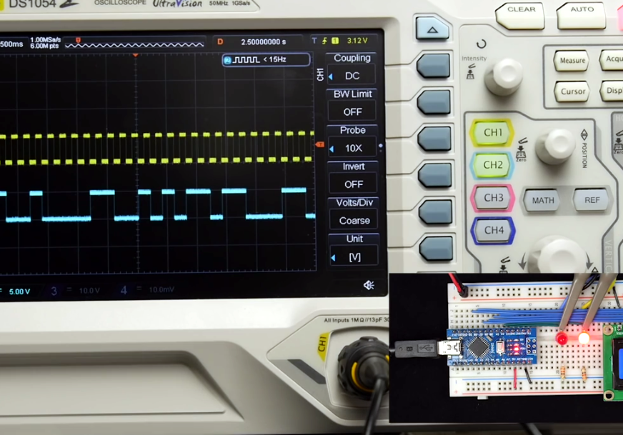
The RFID reader board communicates with the rest of the CatGenie using I2C and he needed to know what was being transmitted. To do that he learned how to use a cheap logic analyzer to read the signals on the I2C wires, which makes this an interesting story. You can see the logic analyser output on his blog and GitHub repository along with mention of a timing issue he ran into. From what he learned, he wrote up Arduino code which sends the same signals. He and his cat are now sitting pretty.

What he didn’t do is make a video. But the CatGenie really is amazing to watch in action as it goes through its rather complex 30-35 minute process so we found a video of it doing its thing, shown at 3.5x speed, and included that below.  If you’re into that sort of thing.

[via Adafruit]

It’s probably fair to say that anyone reading these words understands conceptually how physically connected devices communicate with each other. In the most basic configuration, one wire establishes a common ground as a shared reference point and then the “signal” is sent over a second wire. But what actually is a signal, how do the devices stay synchronized, and what happens when a dodgy link causes some data to go missing?

All of these questions, and more, are addressed by [Ben Eater] in his fascinating series on data transmission. He takes a very low-level approach to explaining the basics of communication, starting with the concept of non-return-to-zero encoding and working his way to a shared clock signal to make sure all of the devices in the network are in step. Most of us are familiar with the data and clock wires used in serial communications protocols like I2C, but rarely do you get to see such a clear and detailed explanation of how it all works.

He demonstrates the challenge of getting two independent devices to communicate, trying in vain to adjust the delays on the receiving and transmitting Arduinos to try to establish a reliable link at a leisurely five bits per second. But even at this digital snail’s pace, errors pop up within a few seconds. [Ben] goes on to show that the oscillators used in consumer electronics simply aren’t consistent enough between devices to stay synchronized for more than a few hundred bits. Until atomic clocks come standard on the Arduino, it’s just not an option.

[Ben] then explains the concept of a dedicated clock signal, and how it can be used to make sure the devices are in sync even if their local clocks drift around. As he shows, as long as the data signal and the clock signal are hitting at the same time, the actual timing doesn’t matter much. Even within the confines of this basic demo, some drift in the clock signal is observed, but it has no detrimental effect on communication.

In the next part of the series, [Ben] will tackle error correction techniques. Until then, you might want to check out the fantastic piece [Elliot Williams] put together on I2C.

[Thanks to George Graves for the tip.]

A good deal of the projects we cover here at Hackaday are not, in the strictest sense, practical endeavors. If we required that everything which graced our digital pages had a clear end result, the site would be in a rather sad state of affairs. Sometimes it’s enough just to do something for the challenge of it. But more often than not, you’ll learn something in the process which you can use down the line.

That’s precisely what pushed [Laurence Bank] to see how well he could optimize the frame rate on the popular SSD1306 OLED display. After several iterations of his code, he was able to achieve a blistering 151.5 FPS, with apparently still some room for improvement if he’s feeling up to the challenge. But considering his first attempt was only running at 5.5 FPS, we’d say he’s already more than earned his hacker cred on this one.

A few different tricks were used to achieve such incredible performance gains. To start with, while the official I2C specification says you’re supposed to wait for an acknowledgment back from the device when communicating with it, [Laurence] realized the SSD1306 didn’t actually care. He could continuously blast commands at the display without bothering to wait for an acknowledgment. He admits there are problems with this method, but you can’t argue with the results.

To really wring all the performance out of the system he could, [Laurence] donned his Assembly Cap and examined how the Arduino IDE compiler was interpreting his code. He identified a few areas where changing his C code would force the compiler to generate faster output. He notes that this wouldn’t normally be required when working with more advanced compilers, but that the Arduino toolchain needs its hand held occasionally.

This isn’t the first time we’ve seen somebody try and push more pixels through the very same OLED display, and it’s interesting to see the two very different approaches to the same goal.

We’re digging these daisy-chainable encoders built by [fattore.saimon]. Each module consists of a rotary encoder attached to a PCB with a PIC16F15386 on the back. As we’ve covered in the past, the Microchip released their feature-rich PIC16 microprocessor just this year, and it’s great to see them start to crop up in projects. With 4 address jumpers on the back of each PCB, [fattore.saimon] is able to connect up to 16 of the encoders on the bus. The modules also have male and female plugs so he can connect them physically as well, to simplify wiring. Each module also has a PWMable bicolor LED for keeping track of each encoder’s setting.

If you’re interested in making your own you can buy the PCBs from Tindie or download the project files from the creator’s GitHub, including an Arduino library.

We love encoders here on Hackaday — building DIY encoders, as well as using them in projects like this precision cutting jig. And definitely read our colleague [Al]’s great piece on encoders.


Filed under: Arduino Hacks

Feel like taking a long walk, but can’t be bothered with carrying your drinks? Have no fear, this  “Follow Me” Cooler Bot is here!

Really just a mobile platform with a cooler on top, the robot connects to smartphone via Bluetooth, following it using GPS. Making the platform involves a little woodworking skill, and an aluminium hub with a 3D-printed hub adapter connects the motors to a pair 6″ rubber wheels with a swivel caster mounted at the rear. A pocket in the platform’s base houses the electronics.

The Arduino Uno — via an L298n motor driver — controls two 12V DC, brushed and geared motors mounted with 3D printed brackets, while a Parallax PAM-7Q GPS Module in conjunction with an HMC 5883L compass help the robot keep its bearing. A duo of batteries power the motors and the electronics separately to prevent  any malfunctions.

Controlling the platform is done on an Android smartphone using Blynk. Ease of use and the ability to set basic commands to be sent to the robot over a desired connection type made it ideal for this helpful little ‘bot.

There isn’t anything more complicated going on — like obstacle avoidance or sophisticated pathfinding — so you kinda need a clear line between you and the cooler. Still, beverage storage is a great feature to add to you tag-along robot companion. It seems to work just fine.


Filed under: Arduino Hacks, gps hacks, robots hacks

[Dan], admirably rose to the occasion when his son wanted a new toy. Being a dedicated father — and instead of buying something new — he took the opportunity to abscond to his workbench to convert a Wiimote Nunchuck into a fully wireless controller for his son’s old r/c car — itself, gutted and rebuilt some years earlier.

Unpacking the nunchuck and corralling the I2C wires was simply done. From there, he combined a bit of code, an Arduino pro mini, and two 1K Ohm resistors to make use of an Aurel RTX-MID transceiver that had been lying around. Waste not, want not.

A TI Stellaris Launchpad is the smarts of the car itself, in concordance with a TB6612FNG motor controller. The two Solarbotics GM9 motors with some 3D printed gears give the car some much needed gusto.

In Dan’s own humble words: “nothing out of the ordinary, just a nice example of what one can do with parts mostly gathering dust around any hacker’s house.” If any new parents out there have a spare Wiimote stashed away, you can use the infrared LEDs to make a fairly effective baby monitor.


Filed under: Arduino Hacks, toy hacks

PJON, pronounced like the iridescent sky rats found in every city, is a cool one wire protocol designed by [gioblu].

[gioblu] wasn’t impressed with the complications of I2C. He thought one-wire was too proprietary, too complicated, and its Arduino implementations did not impress. What he really wanted was a protocol that could deal with a ton of noise and a weak signal in his home automation project with the smallest amount of wiring possible.

That’s where is his, “Padded Jittering Operative Network,” comes in. It can support up to 255 Arduinos on one bus and its error handling is apparently good enough that you can hold an Arudino in one hand and see the signals transmitted through your body on the other. The fact that a ground and a signal wire is all you need to run a bus supporting 255 devices and they’ll play nice is pretty cool, even if the bandwidth isn’t the most extreme.

Aside from the cool of DIY protocols. We really enjoyed reading the wiki describing it. Some of the proposed uses was running your home automation through your ducting or water pipes (which should be possible if you’re really good at isolating your grounds). Either way, the protocol is neat and looks fun to use. Or check out PJON_ASK if you want to do away with that pesky single wire.


Filed under: Arduino Hacks

Historically when hams built low power (QRP) transmitters, they’d use a crystal to set the frequency. Years ago, it was common to find crystals in all sorts of radios, including scanners and handheld transceivers. Crystals are very stable and precise and it is relatively easy to make a high quality oscillator with a crystal and a few parts.

The big problem is you can’t change the frequency much without changing crystals. Making a high quality variable frequency oscillator (VFO) out of traditional components is quite a challenge. However, today you have many alternatives ranging from digital synthesis to all-in-one IC solutions that can generate stable signals in a wide range of frequencies.

[N2HTT] likes to build radio projects and he decided to take an Si5351 clock generator and turn it into a three frequency VFO for his projects. The Si5351 uses a crystal, so it is very stable. However, you can digitally convert that crystal frequency into multiple frequencies over a range of about 8kHz to 160MHz.

The chip has two PLLs that multiply the crystal frequency by a programmable amount. Then you can set each channel to start with the crystal frequency or either PLL and divide it by an integer or a fractional amount. As you might expect, the integer divisions result in a more stable output, but if you really need a particular frequency and can accept some jitter, you can get almost anything you want out of the device.

The device [N2HTT] used is in a tiny 10 pin MSOP package, but there are plenty of inexpensive breakout boards available. You control all the multiplying and dividing by sending configuration data to the chip via I2C. There’s even a software package that can tell you the best settings for the frequencies you want to generate.

One thing of interest is the breadboard the VFO is built on. [N2HTT] used an Arduino and a small display along with an encoder to control the chip. But the chip generates some high frequencies and common wisdom is that solderless breadboards aren’t good for high frequency. Acting on a tip he read in a magazine article [N2HTT] took a bamboo cutting board and then affixed standard solderless breadboards to unetched copper PCB material. He then made sure the PCB ground planes were well connected and grounded. It seems to work (you can see it working in the video below).

The output of the chip is a square wave, so if you wanted to use it for radio applications, you’d probably have to low pass filter the output to get a sine wave. The device is only as accurate as the crystal and will exhibit some phase noise and jitter (especially if you don’t have integer divisions). However, having a wide range programmable frequency source for a few bucks is a great building block for lots of different projects.

In fact, we covered a project to use the same part to implement a digital communications mode a few months ago. There’s also more than one Arduino library out there. Since it is I2C, you can use it with many other processors, too.


Filed under: Arduino Hacks, wireless hacks

[Lewin] wrote in to tell us about a high speed library for Arduino Due that he helped develop which allows interfacing OLED displays that use the SSD1306 display controller, using DMA routines for faster display refresh time.

Typically, displays such as the Monochrome 1.3″ 128×64 OLED graphic display , are interfaced with an Arduino board via the SPI or I2C bus. The Adafruit_SSD1306 library written by [Limor Fried] makes it simple to use these displays with a variety of Arduinos, using either software or hardware SPI. With standard settings using hardware SPI, calls to display() take about 2ms on the Due.

[Lewin] wanted to make it faster, and the SAM3X8E on the Due seemed like it could deliver. He first did a search to find out if this was already done, but came up blank. He did find [Marek Buriak]’s library for ILI9341-based TFT screens. [Marek] used code from [William Greiman], who developed SD card libraries for the Arduino. [William] had taken advantage of the SAM3X8E’s DMA capabilities to enable faster SD card transfers, and [Marek] then adapted this code to allow faster writes to ILI9341-based screens. All [Lewin] had to do was to find the code that sent a buffer out over SPI using DMA in Marek’s code, and adapt that to the Adafruit library for the SSD1306.

There is a caveat though: using this library will likely cause trouble if you are also using SPI to interface to other hardware, since the regular SPI.h library will no longer work in tandem with [Lewin]’s library. He offers some tips on how to overcome these issues, and would welcome any feedback or testing to help improve the code. The speed improvement is substantial. Up to 4 times quicker using standard SPI clock, or 8 times if you increase SPI clock speed. The code is available on his Github repo.


Filed under: Arduino Hacks
Feb
25

HDC1000 temperature and humidity sensor breakout, with Arduino library!

arduino, HDC1000, Humidity, i2c, Sensor, temperature Comments Off on HDC1000 temperature and humidity sensor breakout, with Arduino library! 

DSC_5869-1024x784

by Francesco Truzzi :

Some time ago I came across a new chip from TI, the HDC1000. It’s a temperature and humidity sensor with I2C interface and requires little to no additional components. It comes in an 8BGA package: we can all agree it’s pretty small.
Some of the peculiar characteristics of this chip are that it has a DRDYn pin which goes low any time there is a new reading from the chip (so you can precisely time your requests) and that the sensor is located on the bottom of the IC, so that it’s not exposed to dust and other agents that may false the readings. Also, it has an integrated heater that can remove humidity from the sensor.

So I developed a very small breakout board for this chip as well as an Arduino library (yay, my first one! raspberryPi and nodemcu might come next).

[via]

HDC1000 temperature and humidity sensor breakout, with Arduino library! - [Link]


  • Newsletter

    Sign up for the PlanetArduino Newsletter, which delivers the most popular articles via e-mail to your inbox every week. Just fill in the information below and submit.

  • Like Us on Facebook