This is part of a series titled “Getting Started with Arduino!” by John Boxall – A tutorial on the Arduino microcontrollers, to be read with the book “Getting Started with Arduino” (Massimo Banzi).
The first chapter is here.
Welcome back fellow arduidans!
This week we will continue to examine the features of the DS1307 real time clock, receive user input in a new way, use that input to control some physical movement, then build a strange analogue clock. So let’s go!
Recall from chapter seven, that the DS1307 is also has an inbuilt square wave generator, which can operate at a frequency of 1Hz. This is an ideal driver for a “seconds” indicator LED. To activate this you only need to send the hexidecimal value 0×10 after setting the date and time parameters when setting the time. Note this in line 70 of the solution for exercise 7.1. This also means you can create 1Hz pulses for timing purposes, an over-engineered blinking LED, or even an old-school countdown timer in conjunction with some CMOS 4017 ICs.
For now, let’s add a “seconds” LED to our clock from exercise 7.1. The hardware is very simple, just connect a 560 ohm resistor to pin 7 of our DS1307, thence to a normal LED of your choice, thence to ground. Here is the result:
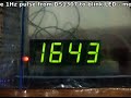
Not that exciting, but it is nice to have a bit more “blinkiness”.
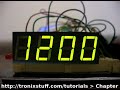
Finally, there is also a need to work with 12-hour time. From the DS1307 data sheet we can see that it can be programmed to operate in this way, however it is easier to just work in 24-hour time, then use mathematics to convert the display to 12-hour time if necessary. The only hardware modification required is the addition of an LED (for example) to indicate whether it is AM or PM. In my example the LED indicates that it is AM.
Exercise 8.1
So now that is your task, convert the results of exercise 7.1 to display 12-hour time, using an LED to indicate AM or PM (or two LEDs, etc…)
Here is my result in video form:
and the sketch: exercise8.1.pdf.
OK then, that’s enough about time for a while. Let’s learn about another way of accepting user input…
Your computer!
Previously we have used functions like Serial.write() and Serial.print() to display data on the serial monitor box in the Arduino IDE. However, we can also use the serial monitor box to give our sketch data. At first this may seem rather pointless, as you would not use an Arduino just to do some maths for you, etc. However – if you are controlling some physical hardware, you now have a very simple way to feed it values, control movements, and so on. So let’s see how this works.
The first thing to know is that the serial input has one of two sources, either the USB port (so we can use the serial monitor in the Arduino IDE) or the serial in/out pins on our Arduino board. These are digital pins 0 and 1. You cannot use these pins for non-serial I/O functions in the same sketch. If you are using an Arduino Mega or compatible board (lucky you) the pins are different, please see here. For this chapter, we will use the USB port for our demonstrations.
Next, data is accepted in bytes (remember – 8 bits make a byte!). This is good, as a character (e.g. the letter A) is one byte. Our serial input has a receiving buffer of 128 bytes. This means a project can receive up to 128 bytes whilst executing a portion of a sketch that does not wait for input. Then when the sketch is ready, it can allow the data to serially flow in from the buffer. You can also flush out the buffer, ready for more input. Just like a … well let’s keep it clean.
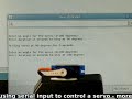
Ok, let’s have a look. Here is a sketch that accepts user input from your computer keyboard via the serial monitor box. So once you upload the sketch, open the serial monitor box and type something, then press return or enter. Load this sketch, example 8.1.pdf. Here is a quick video clip of it in operation:

Notice in the line Serial.print(character, BYTE); that we force the display to byte, this is to show the value as the matching ASCII character; otherwise it would return the ASCII value of the character instead. For the young ones out there, please read this for an explanation of the ASCII table.
So now we can have something we already know displayed in front of us. Not so useful. However, what would be useful is converting the keyboard input into values that our Arduino can work with.
Consider this example – example 8.2.pdf. It accepts an integer from the input of serial monitor box, converts it to a number you can use mathematically, and performs an operation on that number. Here is a shot of it in action:

If you are unsure about how it works, follow the sketch using a pen and paper, that is write down a sample number for input, then run through the sketch manually, doing the computations yourself. I often find doing so is a good way of deciphering a complex sketch. Once you have completed that, it is time for…
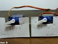
Exercise 8.2
Create a sketch that accept an angle between 0 and 180, and a time in seconds between 0 and (say) 60. Then it will rotate a servo to that angle and hold it there for the duration, then return it to 0 degrees. For a refresher on servo operation, visit chapter three before you start.
Here is a video clip of my interpretation at work:
and the example solution sketch: exercise 8.2.pdf
So now you have the ability to generate user input with a normal keyboard and a PC. In the future we will examine doing so without the need for a personal computer…
Finally, let’s have some fun by combining two projects from the past into one new exercise.
Exercise 8.3
Create an analogue clock using two servos, in a similar method to our analogue thermometer from chapter three. The user will set the time (hours and minutes) using the serial monitor box.
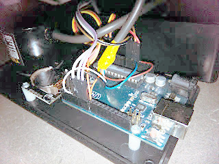
Here is a photo of my example. I spared no expense on this one…

And of course a video demonstration. First we see the clock being set to 12:59, then the hands moving into position, finally the transition from 12:59 to 1:00.
If you had more servos and some earplugs, a giant day/date/clock display could be made… If you like different clocks, have a look at these kits.
Nevertheless, we have had another hopefully interesting and educational lecture. Or at least had a laugh
Another week over. I apologise for this chapter being a little shorter than usual, unfortunately we have some sickness in the family. However, as usual I’m already excited about writing the next instalment… Congratulations to all those who took part and built something useful! Please subscribe (see the top right of this page) to receive notifications of new articles. High resolution photos are available from flickr.
If you have any questions at all please leave a comment (below). We also have a Google Group dedicated to the projects and related items on the website – please sign up, it’s free and we can all learn something -
If you would like to showcase your work from this article, email a picture or a link to john at tronixstuff dot com.
You might even win a prize. Don’t forget to check out the range of gear at Little Bird Electronics!
So have fun, stay safe and see you soon for our next instalment!


 Behind the clock is an Arduino driving a MAX7219 LED controller. Using the MAX7219 was a challenge because it expects a grid of LEDs while the clock needs a linear array. [Dylan] used a line of individual LEDs wired to match what the controller wanted. A rotary encoder tells the processor the position of the arm so the Arduino sketch can determine which LEDs should be lit to show the time and clock face.


