
06
Analog panel meters (APM) are instruments that measure and display variables on a dial, usually with a moving pointer or needle in front of a proportional scale.
I wanted to try using these meters in a clock project but have been put off by their high unit cost. However, a recent ‘fire sale’ at a local electronics wholesaler provided the opportunity to acquire 10 meters for just a few cents each, so this project became feasible.

All the files and software for this project are available online at my code repository.
The concept for this clock is to display the clock’s date and time elements on a number of separate meters, each driven by the voltage produced by the microcontroller analog output.
Analog Panel Meters
Panel meters are simple electromechanical devices that can be used to measure currents, voltages, and resistances.
The basic part of any meter is the movement (a moving coil with associate mechanical pivots and adjusters). The movement moves the needle over the calibrated range to indicate the quantity being measured.

The coil works as a simple electromagnet – if you apply a voltage to the coil and a current flows through it, it magnetizes its iron core and creates a magnetic field that moves the pointer in proportion to the voltage applied. A spring holds tension on the movement to balance the electromagnetic force and return it to the zero position when no voltage is applied.
A good video of how meters work can be found here.
The panels meters I purchased (Jaycar QP5020) are designed to measure a full-scale deflection of 20V DC, but the maximum analog output from the microcontroller is 5V, so something needed to be modified.
Meter Recalibration
Most panel meters are just a raw movement, with a certain sensitivity, often written on the lower portion of the scale. Typical wording would be “10 mA FS” to indicate that the meter needs a 10mA current through it for full scale deflection. This full scale current usually has no relation to the indicator scale markings.
To recalibrate the meter you need to adapt the resistance of the driving circuitry to achieve the full scale current of the panel meter with the new driving voltage. You can see in the photo below that, for the volt meter used in this project, there was an internal resistor in series with the + terminal used to calibrate the meter.

For the as-purchased full scale range (1mA from the meter specs), the 20V reading was achieved with a 20kΩ resistor in series with the measured voltage. By Ohms Law (I=V/R) this gives a full scale current of (20V/20kΩ) = 1mA. So, reversing the calculation, to show a full scale voltage of 5V – the maximum Arduino analog output – we need to replace the resistor with a (5V/1mA) = 5kΩ resistor.
Changing Meter’s Faceplate
Once the range is changed the original panel meter indicator scale becomes obsolete, so it needs a new faceplate. In any case I wanted to show time and date values, not voltages, so I went searching for software that could help with this task.

I found 2 commonly referenced/recommended specialist tools that run under Microsoft Windows:
- Meter (link here) has a paid and free version. The free MeterBasic (a cut down version of the paid version) is sufficient for a hobbyist who needs to generate the occasional simple scale. It is based on a subset of the features found in Meter and has no time or usage limitations. The design of the scale/faceplate is based on input entered into fixed parameter fields, with a draft displayed in the application window before printing it out.
- Galva (link here) is a free program that was specifically designed to draw precise dials for galvanometers, potentiometer, CVs, and other dial-type devices, although it is now more general. It can draw scales with all kinds of shapes (curved or straight) and graduations (linear, functions of a power, logarithmic, specific, manual, etc.). Scales are produced using a scripting language with an on-screen graphical preview before printing.
After experimenting with both I decided to use Galva. The learning curve was much steeper but it seemed to be more flexible and the output looker cleaner on my printer. The script used to produce the scales shown below is included within in the project sketch source folders.

MCU Analog Output
On thing to note is that the MCU ‘analog’ output is really a PWM output, which means that the meter is not measuring a constant voltage but an oscillating square wave.
I ran some tests with the meters used in this project and they did not seem to be affected by this (ie, setting the voltage to a known value showed the approriate proportional movement of the meter dial). However, this may not be the case for other meters and will need to be determined on a case by case basis. The solution would be to smooth out the voltage with a capacitor – lots on material on the internet for this.
It is also worth noting that USB power supplies are not usually exactly 5V and therefore the MCU output cannot be exact, creating errors in the full scale deflection of the meter. There are a couple of easy solutions for this:
- Ensure that the voltage is correct. My experience is that a USB power supply is usually just under 5V, so this is the option I used. By adding by adding in a step-up buck converter at the USB power input to the clock, I ensure that the voltage remains at exactly 5V for ll the clock circuits. This makes the internal voltage independent of the supply voltage as long as it is 5V or less. If your usual supply is greater that 5V then a step-down buck converter could be used to the same effect.
- Match the internal resistance to the expected voltage (eg, use an adjustable variable resistor instead of a fixed value). This works well for an arbitrary voltage but only for that specific voltage. Should the voltage fluctuate it will stop working and need readjusting.
System Hardware
Once I was sure that the concept was valid, it was time to consider the system architecture.

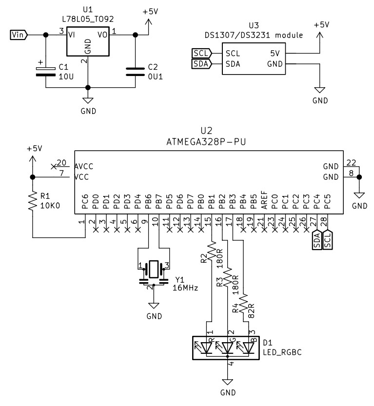
The clock is powered through a USB power-only socket. A step-up voltage converter is used to maintain the calibrated, accurate, constant 5V for the clock circuits.
The RTC time clock is a DS3231 module with an I²C interface. The APM displays month, date, day of week, hours and minutes on the meter dials APM1 through APM55.
Finally, two momentarily-on switches (for Mode and Set) are used for setting and displaying the time.


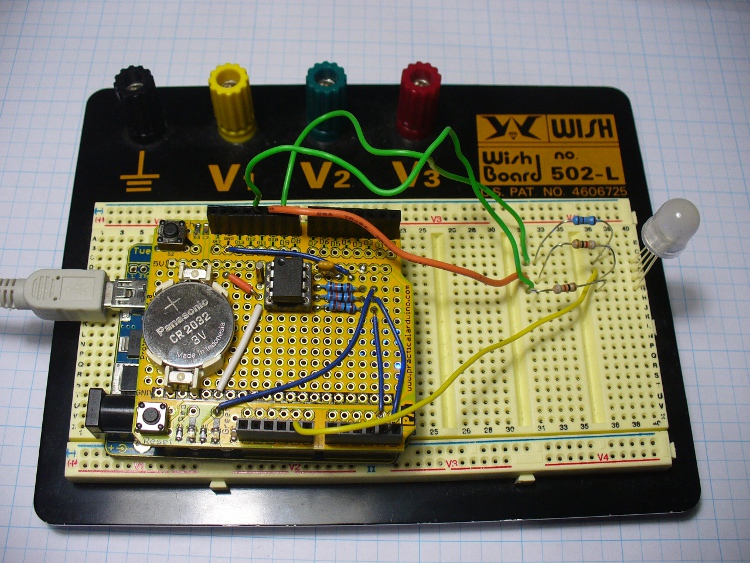
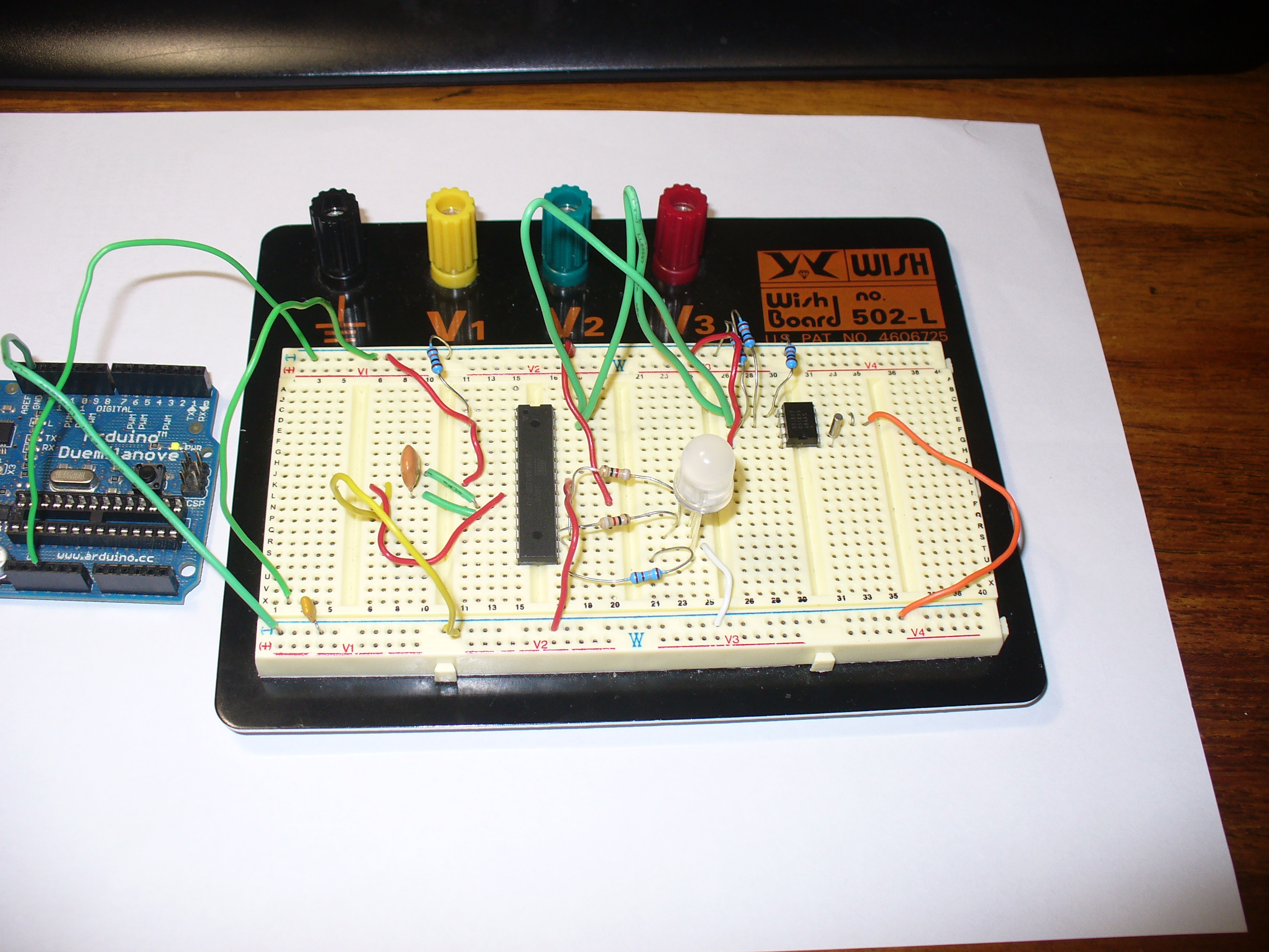
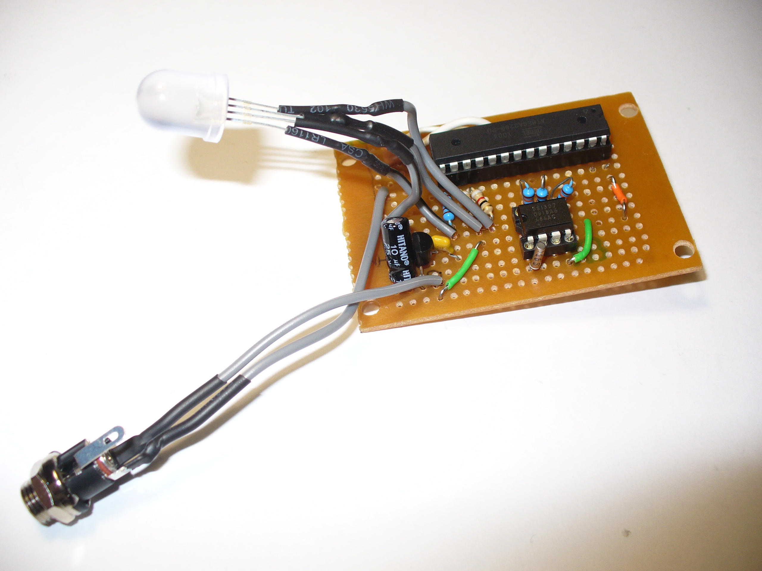
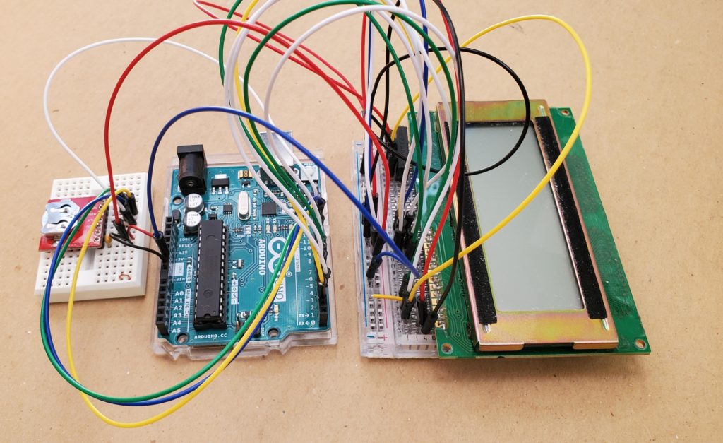
The hardware was prototyped using my existing prototyping modules (see this previous blog post) modules and an Arduino Uno, shown below.

Clock Case
Front Panel and Enclosure
For this project the case is made from three parts – a perspex front panel, plywood sides and a removable plywood back.
The perspex front panel was drawn in Fusion360 to produce a 1:1 paper template that allowed me to easily drill out the holes for the APMs. This does not need to be too neat as the holes are hidden behind the APM faces and the outside edges are covered by the enclosure face frame when installed.
The inside of the transparent perspex panel was sanded and spray painted black to produce the effect shown in the photos below.


The sides are a simple 12mm plywood box with a mitred face frame. The perspex panel was butted to the inside of the face frame and fixed in place with a bead of hot glue around the inside edge join in the box.
The back (not shown) is 3mm plywood attached with M3 machine screws into threaded inserts installed on the edge of the plywood box. The back has a cut out to install the USB connector and two tact switches.
Switches and Power Connection
A 3D printed part was produced as a scaffold for the USB connector and Mode/Set switches. This was modelled in Fusion 360, shown below.


The 3D model for this is included in the project files.
Software
To simplify software implementation I used my MD_DS3231 and MD_UISWitch libraries to manage the DS3231 RTC and the switches using the Arduino Pro Mini.
The software for this project is available from my code repository. Essentially it does 4 things:
- Periodically update the display. Checks every second and updates when the minutes change.
- Manage time setup progression when the mode switch is pressed.
- Manage Summer Time offset when the mode switch is long pressed.
- Display full range on all APM when the Set switch is pressed.
Display Update
The clock does not show seconds, so the minimum time resolution is 1 minute. The RTC is checked and the display updated every second by counting elapsed milliseconds.
Time Setup
The actual time needs to be input at the start and, from time to time, may need adjusting.
Adjusting the time is started by pressing the Mode switch to move between each APM, the Set switch to increment the value displayed, with roll-around, and the the Mode switch to move on to the next value to be changed. To show which APM is being the ‘current’ value being changed, all the other meter displays are set to zero.
Displays are updated in the order month, date, day of week, hour and minute. As this clock has a 12 hour dial, while the hours are being edited the minute display will move to zero if the hours are in the morning (AM) and move to full scale when the hours are PM.
P:ressing Mode after the last value (minutes) is set will set the time. A one minute inactivity timeout prevents the display from remaining in edit mode indefinitely – the time setting process is aborted and the new time is not set.
Summer Time Offset
Rather than go through the process of setting a new time the Summer Time period, a long press of the mode switch will set up an automatic +1 hour display offset to the RTC time. Summer Time offset is reset to +0 by another long press. The current Summer Time mode is stored in EEPROM and will be retained between power cycles.
Full Range Check
It is useful to occasionally check the full range is accurate. While the clock is displaying the time, pressing the Set switch moves the APM needles to full scale. Releasing the Set switch puts the clock back in normal display mode.
Putting it all together
Once the meters were installed in the enclosure, a ground wire was connected to all the – terminals and a lead to all the + terminals.

The USB and switch module was hot glued to the back panel. The hot glue was also spread over the switch connections to provide some mechanical stability for the wires.


The USB connector and the switch were added to the back panel and wired in. Hot glue was again used to lock the USB socket in place and reinforce the wire connections on the back.
All wires were then soldered to the Pro Mini and it, and the clock module, were hot glued to the base of the enclosure.
The entire was then unit tested before finally closing the case and putting the new clock on the shelf in my office.

